Heat exchanger and its manufacturing method

A technology for heat exchangers and manufacturing methods, which is applied in the field of heat exchangers with a laminated structure, can solve problems such as reduced heat exchange efficiency, reduced mass production, and poor production, so as to reduce processing steps, prevent airflow leakage, and reduce parts Quantity effect

Active Publication Date: 2009-04-08
PANASONIC CORP
View PDF1 Cites 41 Cited by
  • Summary
  • Abstract
  • Description
  • Claims
  • Application Information

AI Technical Summary

Problems solved by technology

In this way, there is a problem that the heat exchange efficiency decreases due to the incorrect formation of the ventilation path on each heat transfer plate 102 due to the wrong stacking of the gaskets 101, and it is required to prevent the heat exchange caused by the inability to correctly form the ventilation path. efficiency reduction
[0009] In addition, since

Method used


Image

  • Heat exchanger and its manufacturing method
  • Heat exchanger and its manufacturing method
  • Heat exchanger and its manufacturing method

Examples


Embodiment approach 1

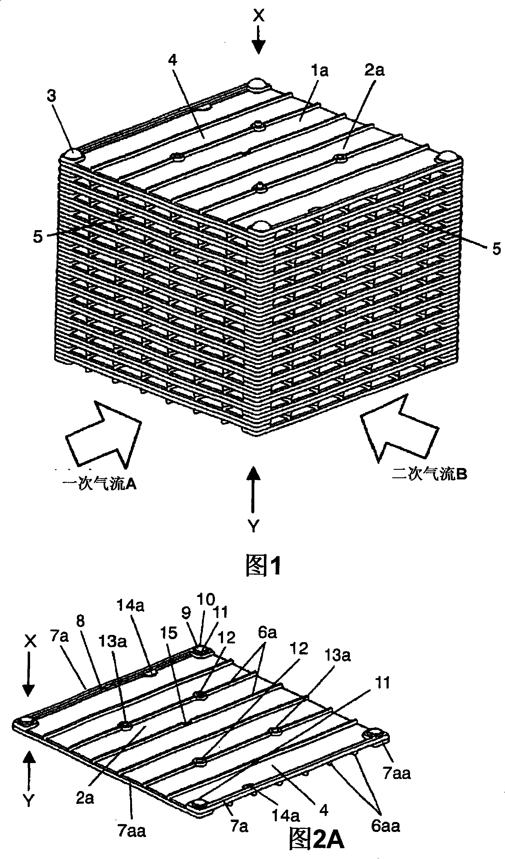
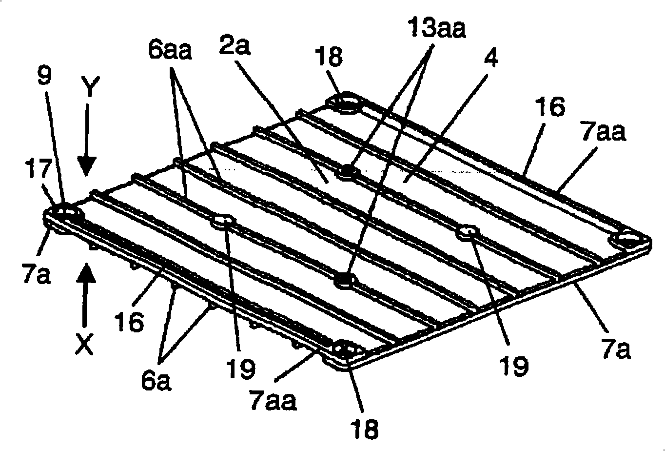
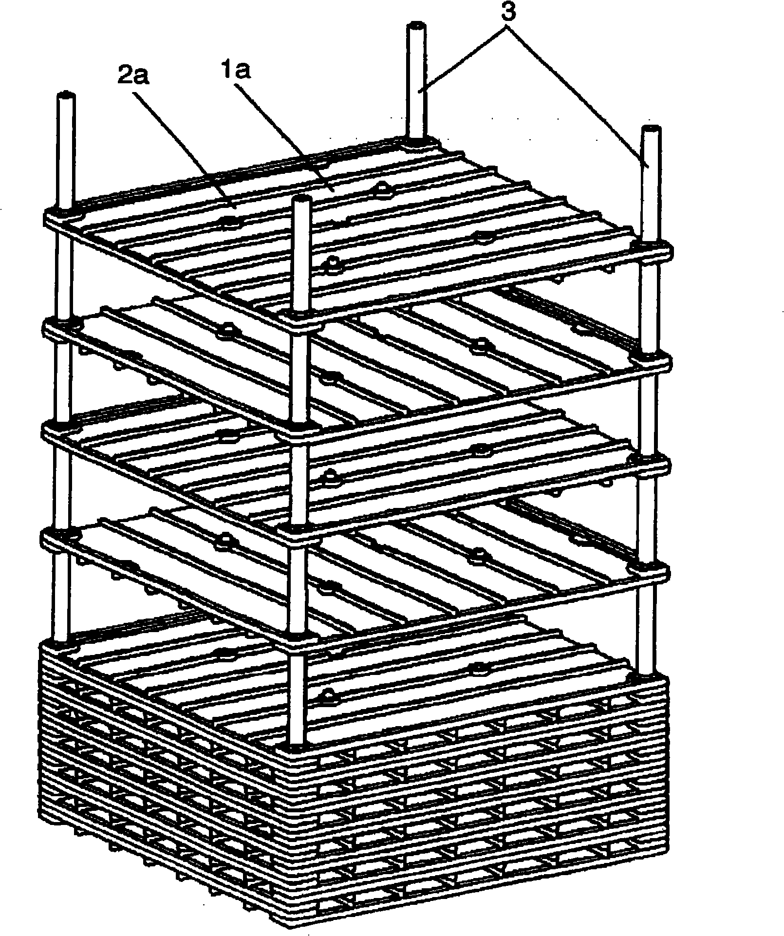
[0097] Fig. 1 is a schematic perspective view of a heat exchanger in Embodiment 1, and Fig. 2A is a schematic perspective view of a unit element viewed from the X direction shown in Fig. 1 , Figure 2B It is a schematic perspective view of the unit cell seen from the Y direction shown in FIG. 1 . image 3 It is a schematic exploded perspective view of the heat exchanger shown in FIG. 1 . Figure 4A It is a schematic perspective view of a heat exchanger showing unit elements of the heat exchanger shown in FIG. 1 stacked correctly, Figure 4B yes Figure 4A A schematic perspective view of the heat exchanger shown in section 4B-4B, Figure 4C yes Figure 4B A schematic enlarged perspective view of the circled portion in . Figure 5A It is a schematic perspective view of a heat exchanger in which the unit elements of the heat exchanger shown in FIG. 1 are erroneously stacked, Figure 5B yes Figure 5A A schematic enlarged perspective view of the circled portion in .

[0098...

Embodiment approach 2

[0167] FIG. 14 is a schematic perspective view of a heat exchanger in Embodiment 2. FIG. Fig. 15A is a schematic perspective view of the unit element seen from the X direction shown in Fig. 14, Figure 15B It is a schematic perspective view of the unit cell seen from the Y direction shown in FIG. 14 . Figure 16A It is a schematic perspective view of a heat exchanger in which the unit elements of the heat exchanger shown in FIG. 14 are correctly stacked, Figure 16B yes Figure 16A A schematic perspective view of the heat exchanger shown in section 16B-16B, Figure 16C yes Figure 16B A schematic enlarged perspective view of the circled portion in .

[0168] Figure 17A It is a schematic perspective view of a heat exchanger in which unit elements of the heat exchanger shown in FIG. 14 are mistakenly stacked, Figure 17B yes Figure 17A A schematic perspective view of the heat exchanger shown in section 17B-17B, Figure 17C is Figure 17B A schematic enlarged perspective...


PUM


Abstract

The present invention provides a heat exchanger for exchanging heat through heat transfer plates by flowing a primary airflow and a secondary airflow in air passages. The heat exchanger comprises a unit element having a heat transfer plate and an air passage formed between the heat transfer plates by stacking the unit elements. Each of the unit elements is structured by molding a space rib for holding the space between the heat transfer plates integrally with a shield rib for shielding the leak of the airflows by use of a resin. The unit element includes an error detection part which can easily detect an error in stacking when the unit elements are stacked.

Description

technical field [0001] The present invention relates to a heat exchanger with a laminated structure used in a heat-exchange ventilation fan for households and a total heat-exchange ventilator for buildings and the like, and a method for manufacturing the same. Background technique [0002] Heretofore, this type of heat exchanger has been formed by laminating heat transfer plates and gaskets without joining, in order to improve basic functions such as ventilation resistance and heat exchange efficiency while reducing manufacturing costs. For example, it is disclosed in Patent Document 1. Below, refer to Figure 20A , Figure 20B , Figure 21 This heat exchanger will be described. [0003] As shown in these figures, the spacer 101 made of synthetic resin is arranged on the spacer ribs 103 and the connection ribs 104 by spacer ribs 103 for maintaining the space between the heat transfer plates 102 and the connection ribs 104 for connecting the spacer ribs 103 to each other. ...

Claims


Application Information

Patent Timeline
IPC IPC(8): F28F3/08F28F3/00
Inventor 村山拓也
Owner PANASONIC CORP
Why Eureka
Try Eureka