Computed tomography data acquisition apparatus and method

A technology of tomography and projection data, applied in the direction of measuring devices, diagnosis, echo tomography, etc.

Inactive Publication Date: 2009-04-08
KONINKLIJKE PHILIPS ELECTRONICS NV
View PDF1 Cites 23 Cited by
  • Summary
  • Abstract
  • Description
  • Claims
  • Application Information

AI Technical Summary

Problems solved by technology

Although these detectors can be used to image relatively large objects, the r...

Method used


Image

  • Computed tomography data acquisition apparatus and method
  • Computed tomography data acquisition apparatus and method
  • Computed tomography data acquisition apparatus and method

Examples


Embodiment Construction

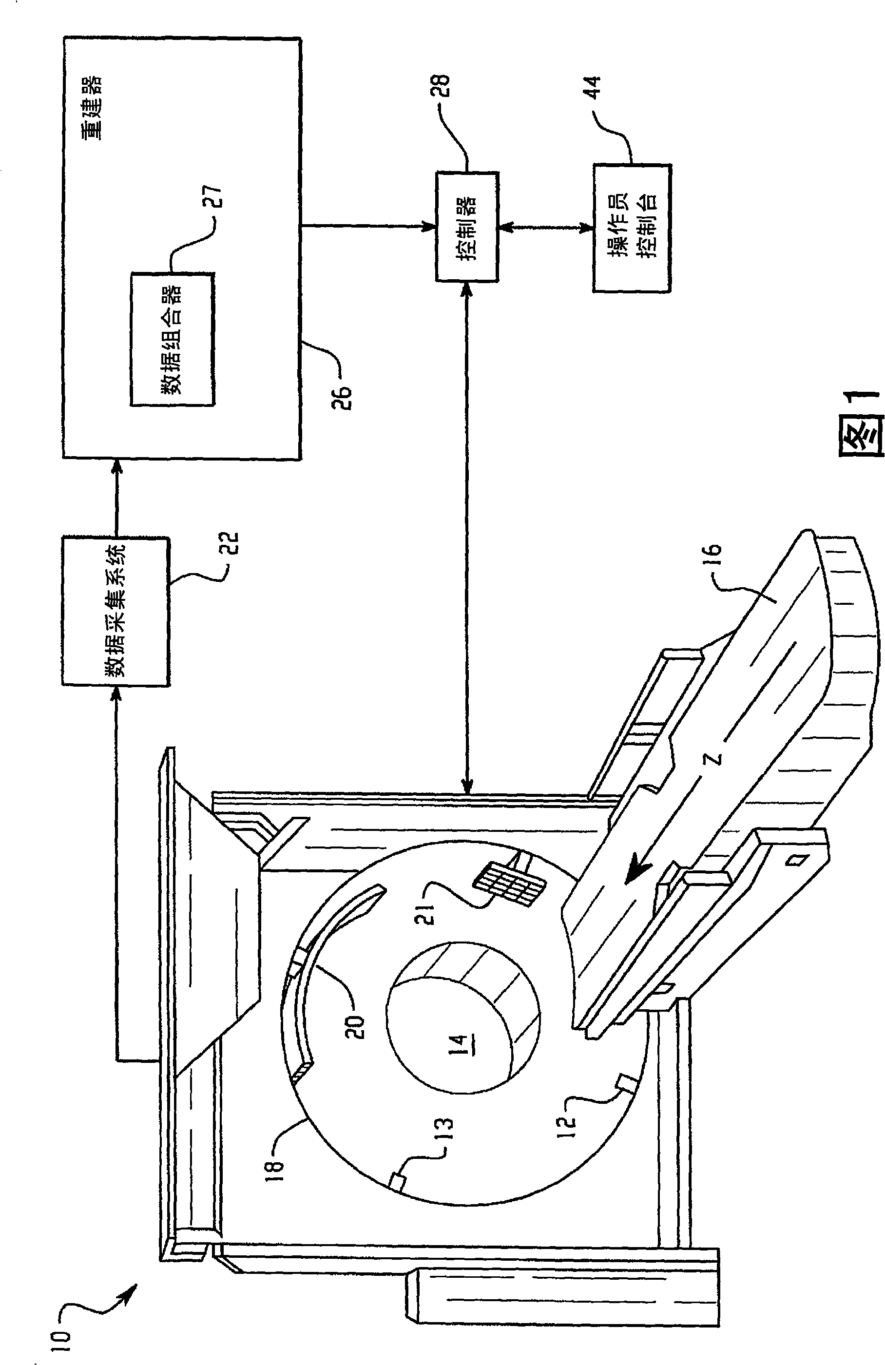
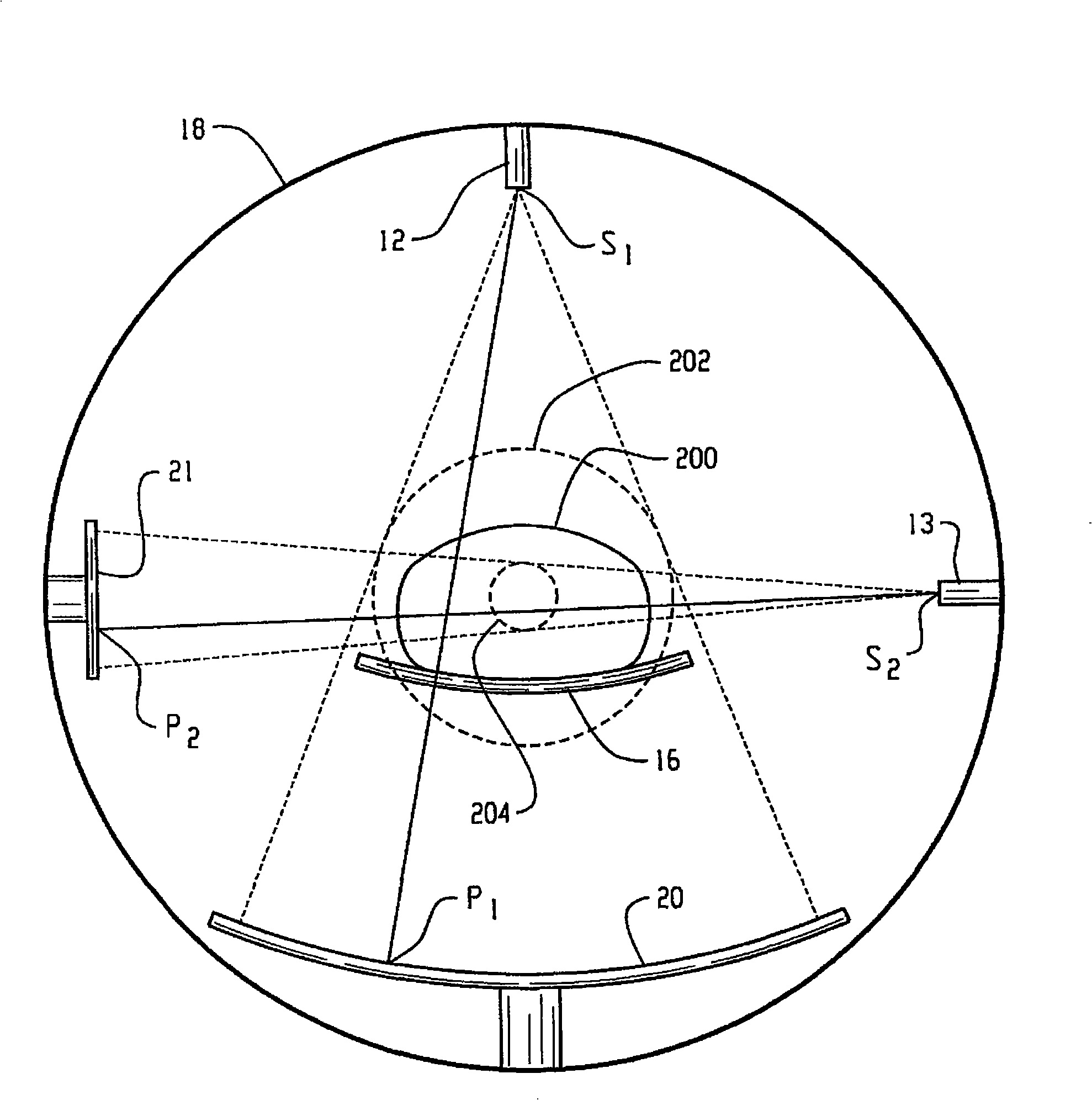
[0020] Referring to FIG. 1 , a CT scanner 10 includes a turret 18 that rotates about an examination region 14 . The rotating frame 18 supports a first radiation source 12 , such as an x-ray tube, and a first x-ray sensitive detector 20 subtending arcs on opposite sides of the examination region 14 . The rotating frame 18 also supports a second x-ray source 13 and a second x-ray sensitive detector 21 . The x-rays generated by the x-ray sources 12 , 13 pass through the examination region 14 and are detected by the detectors 20 , 21 . The detectors 20, 21 then generate first and second projection data representing the detected radiation, respectively.

[0021] The first detector 20 is characterized by a relatively low axial resolution and a relatively large axial field of view. In one implementation, the detector comprises an arcuate array of detector elements 100 arranged in a plurality of longitudinal rows or slices and transverse columns. In one implementation, the detector...


PUM


Abstract

A computed tomography scanner includes a first (20) and second (21) detectors. The second detector (21) has a relatively higher spatial resolution and a relatively smaller field of view (204) than that of the first detector (20). Projection data generated by the detectors (20, 21) is combined and reconstructed so as to generate relatively high resolution volumetric data (318) indicative of a region of interest (314) in an object under examination.

Description

technical field [0001] The present application relates to radiographic imaging techniques, and in particular to techniques for reducing the effects of truncation artifacts caused by detectors with relatively limited fields of view. The present application finds particular application in x-ray computed tomography (CT), especially where it is desired to produce high resolution images of a limited region of interest (ROI). Background technique [0002] CT scanners have proven to be invaluable in providing information representing the internal structure of an object. In medical imaging, for example, CT scanners are widely used to provide images and other information about a patient's physiology. Typically, information generated by a CT scan is reconstructed to produce volume data, which is then represented in one or more human-readable images. [0003] The recent trend has been the rapid adoption of multislice CT and the move to systems with faster rotation speeds. As a resul...

Claims


Application Information

Patent Timeline
IPC IPC(8): G01T1/29G01T1/164
CPCA61B6/482A61B6/032G01T1/2985G01T1/1648A61B6/4014
Inventor A·齐格勒T·尼尔森
Owner KONINKLIJKE PHILIPS ELECTRONICS NV
Why Eureka
Try Eureka