Clamp for cloth

A cloth clamping and horizontal plate technology, applied in the field of cloth clamps, can solve the problems of uneven test cloth force, easy crushing of test cloth, and inability to test, so as to improve reliability, improve reliability and stability, even force effect

Inactive Publication Date: 2009-04-15
TAI WAH INDAL EQUIP SUPPLIES
View PDF1 Cites 4 Cited by
  • Summary
  • Abstract
  • Description
  • Claims
  • Application Information

AI Technical Summary

Problems solved by technology

[0005] The pressure plate 4' rotates with the pressure plate fixing seat 3' as the fulcrum, that is, it rotates and presses the test cloth placed on the top plate 2'. The test cloth is easy to be crushed, and the force of the test cloth is uneven.
[0006] When the button is at the edge of the clothes, the pressing plate 4' cannot fully compress the fabric B' and a virtual position S appears, as shown in Figure 2, and the test cannot be performed at this time

Method used


Image

  • Clamp for cloth
  • Clamp for cloth
  • Clamp for cloth

Examples


Embodiment approach 1

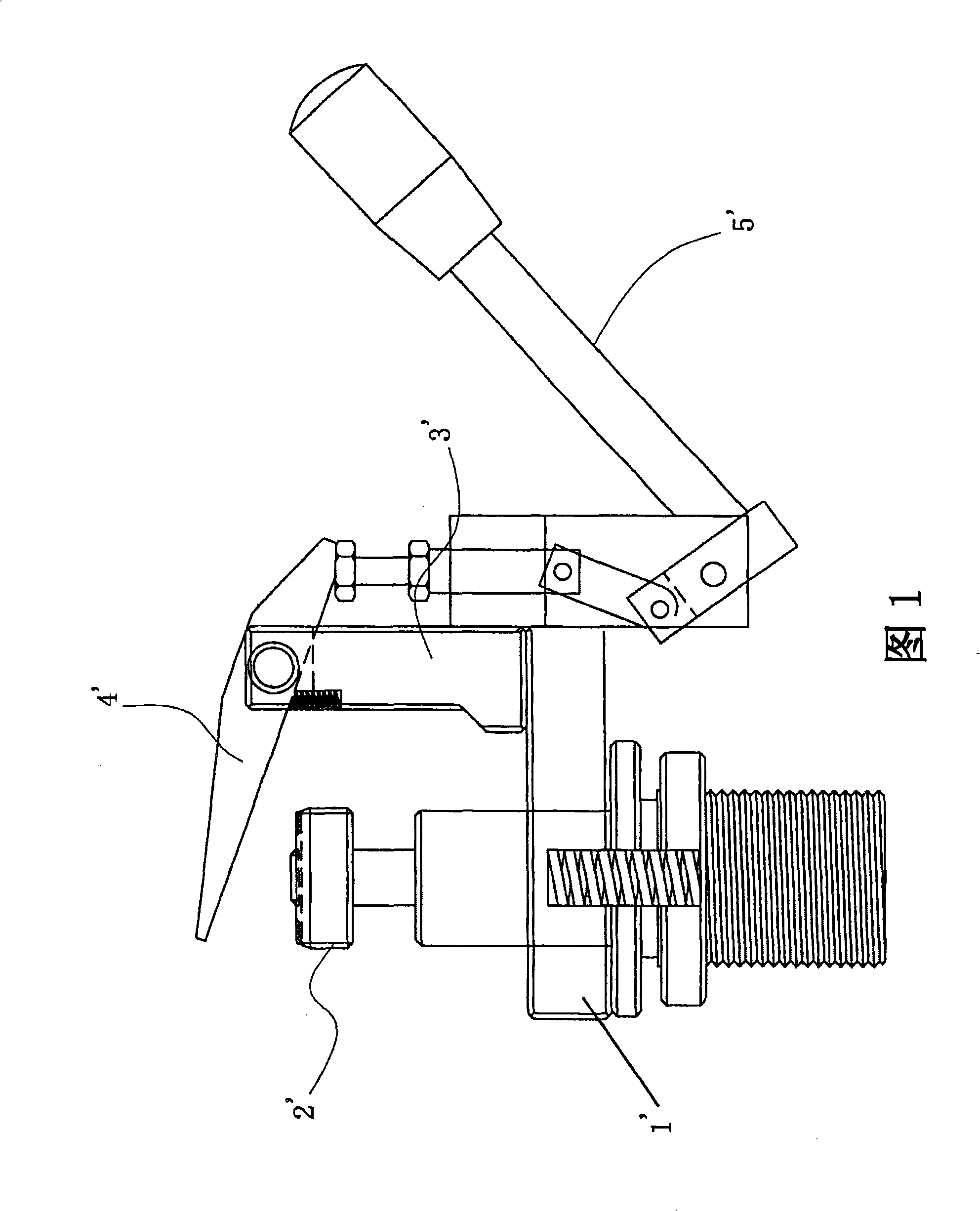
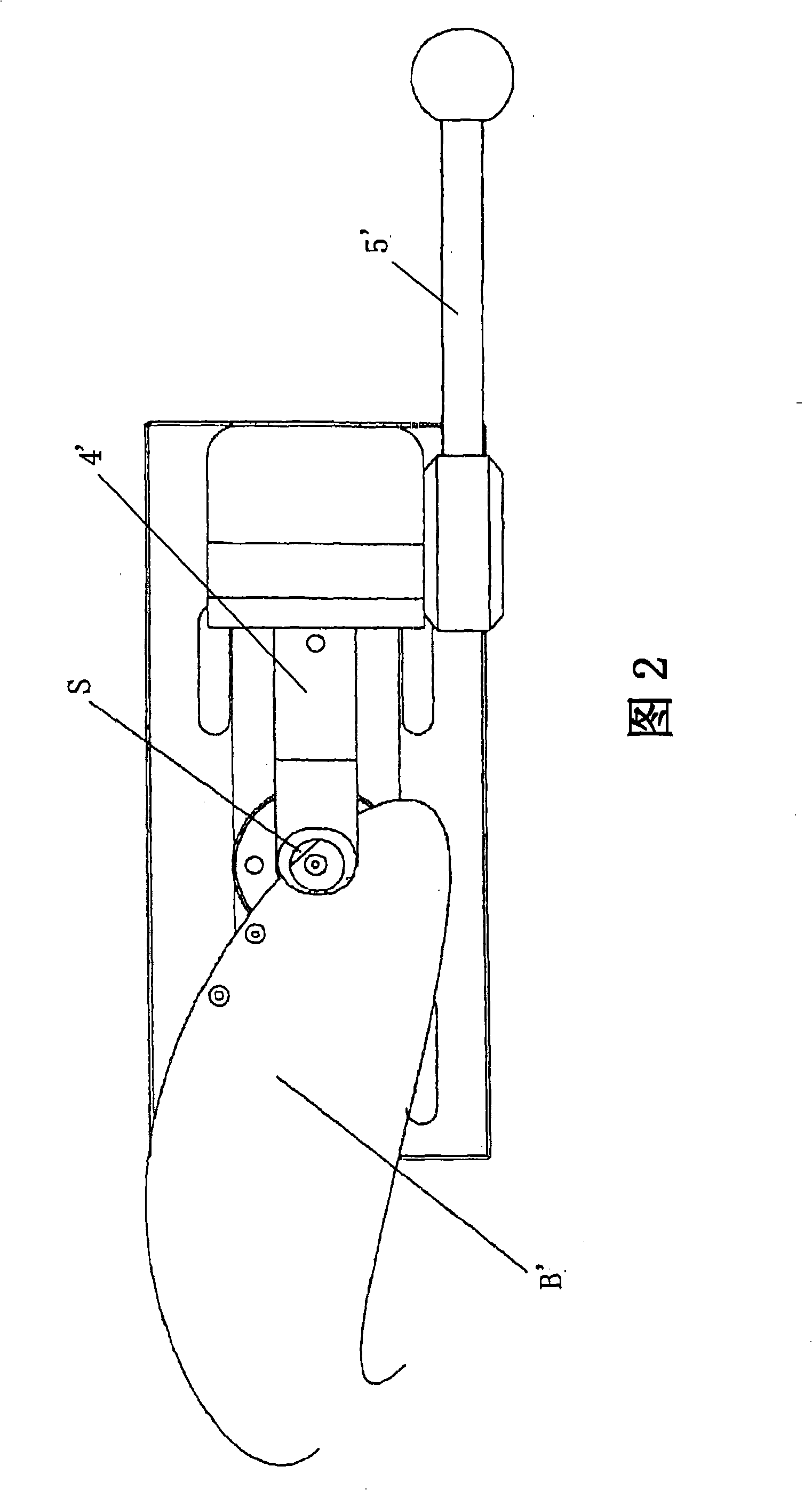
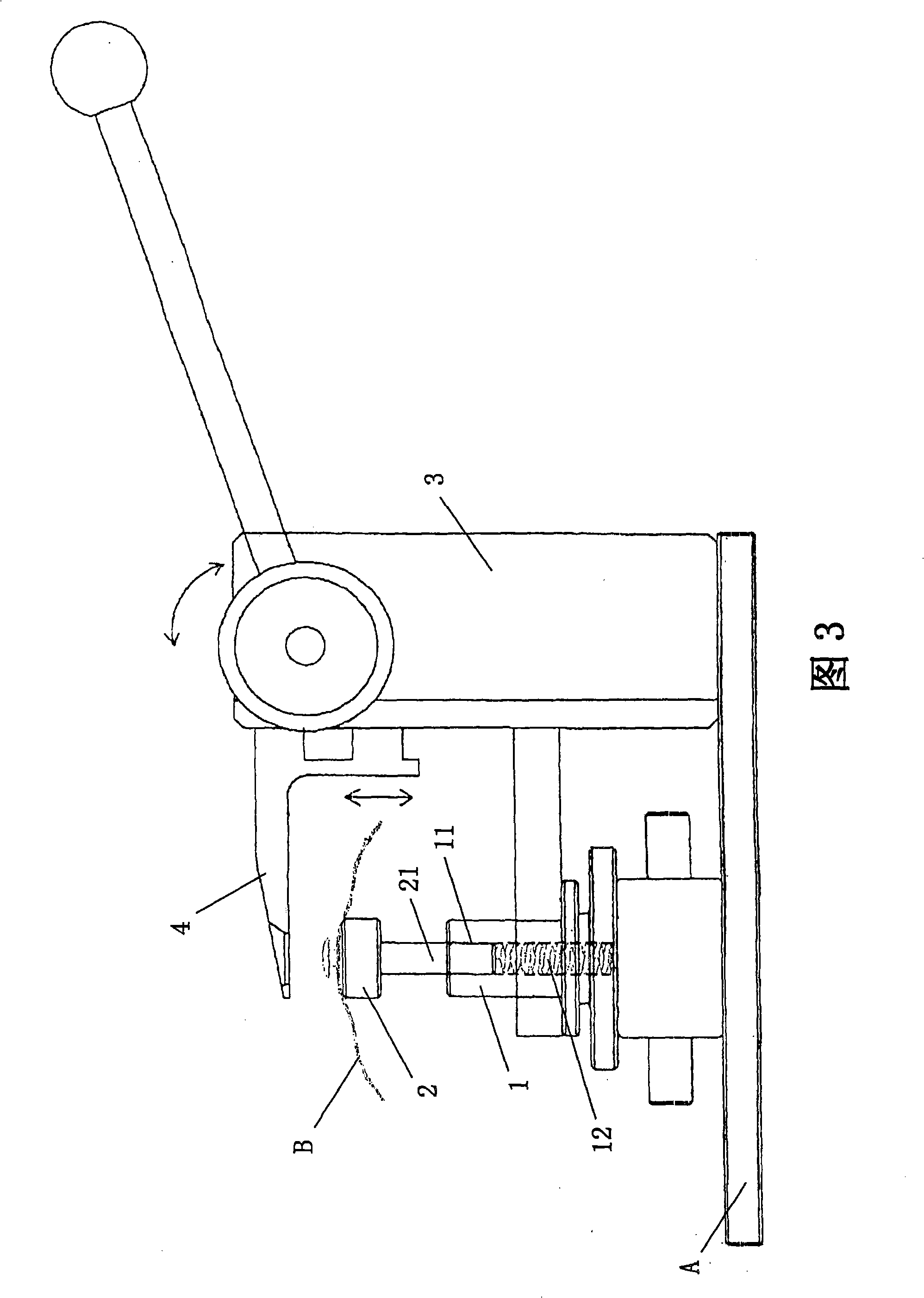
[0037] As shown in Figures 3-8, the cloth clamp pliers proposed by an embodiment of the present invention includes a fixed seat 1 that is convenient to be fixedly connected with other equipment (such as a tension machine base A), and is used for placing a test sample B (cloth for clothing) The positioning plate 2 is elastically connected to the fixed seat 1, and its top protrudes from the top of the fixed seat 1. In this embodiment, an insertion hole 11 is provided on the upper part of the fixing base 1, and an elastic element 12 is arranged inside the insertion hole 11. The column 21 of the positioning plate 2 is partially inserted into the insertion hole 11 and supported on the upper part of the elastic element 12. . The top of the positioning plate 2 adopts elastic and non-slip material, which can be non-metallic material, so as to increase the tightness and prevent the test sample from slipping away. Wherein the elastic element 12 can be a spring, more specifically a comp...

Embodiment approach 2

[0043] The difference between this embodiment and Embodiment 1 is that the combination of the operating handle 5, the support shaft 32 and the coupling block 6 is different. It is also fixedly connected, and when the operating handle 5 rotates, it drives the support shaft 32 to rotate together, and further drives the joint block 6 to rotate synchronously.

[0044] Other structures, working principles, and beneficial effects of this embodiment are the same as those of Embodiment 1, and will not be repeated here.


PUM


Abstract

The invention discloses a fabric clamp, which comprises a permanent seat which is conveniently and fixedly connected with other equipment, a positioning plate and a horizontal plate used for fixedly testing a sample, and an operating device for driving the horizontal plate to act, wherein the positioning plate is arranged on the permanent seat, and the top of the positioning plate is protruded out of the top of the permanent seat; the horizontal plate and the operating device are connected with the permanent seat of the horizontal plate; and the horizontal plate is driven by the operating device and is connected with the permanent seat of the horizontal plate in a vertical lifting mode on the whole. Therefore, the horizontal plate is operated in the vertical lifting mode, and a test sample is fixed until the horizontal plate is pressed on the positioning plate, so that the test sample can not be damaged.

Description

technical field [0001] The invention relates to a cloth clamp, in particular to a cloth clamp used for detecting whether a garment accessory is firmly fixed. Background technique [0002] With the improvement of living standards and the development of science and technology, people's aesthetic views are also changing. Therefore, many ready-to-wear clothes on the market are equipped with some decorations, such as buttons, metal or other hard materials. Decorations, although these decorations are fixed on the fabrics such as garments or shoe uppers by mechanical pressure, these decorations are easy to fall off under the action of external force during use, and children are easy to swallow the decorations, causing life-threatening, so At present, some products have been recalled after being put into the market because the decorations are easy to fall off and cause danger. But along with the change of people's aesthetic point of view, the lack of these decorations will lead to ...

Claims


Application Information

Patent Timeline
Patent Type & Authority Applications(China)
IPC IPC(8): A41H43/00G01N3/04G01N3/08G01N19/00
Inventor 张海日
Owner TAI WAH INDAL EQUIP SUPPLIES
Why Eureka
Try Eureka