Service component

A technology of service components and snap-fit ​​components, which is applied in the field of service components, can solve the problems of not being able to grasp the fastening bolts and the difficulty of locking service components, and achieve the effect of a simple and robust structure

Active Publication Date: 2009-04-15
SAURER GERMANY GMBH & CO KG
View PDF1 Cites 4 Cited by
  • Summary
  • Abstract
  • Description
  • Claims
  • Application Information

AI Technical Summary

Problems solved by technology

[0005] The snapping mechanisms of these known service assemblies have the disadvantage that the snapping of service assemblies that are not correctly positioned or not yet fully locked at the station requiring service is often quite difficult
In other words, especially when the service assembly is still in motion, it sometimes happ

Method used


Image

  • Service component
  • Service component
  • Service component

Examples


Example Embodiment

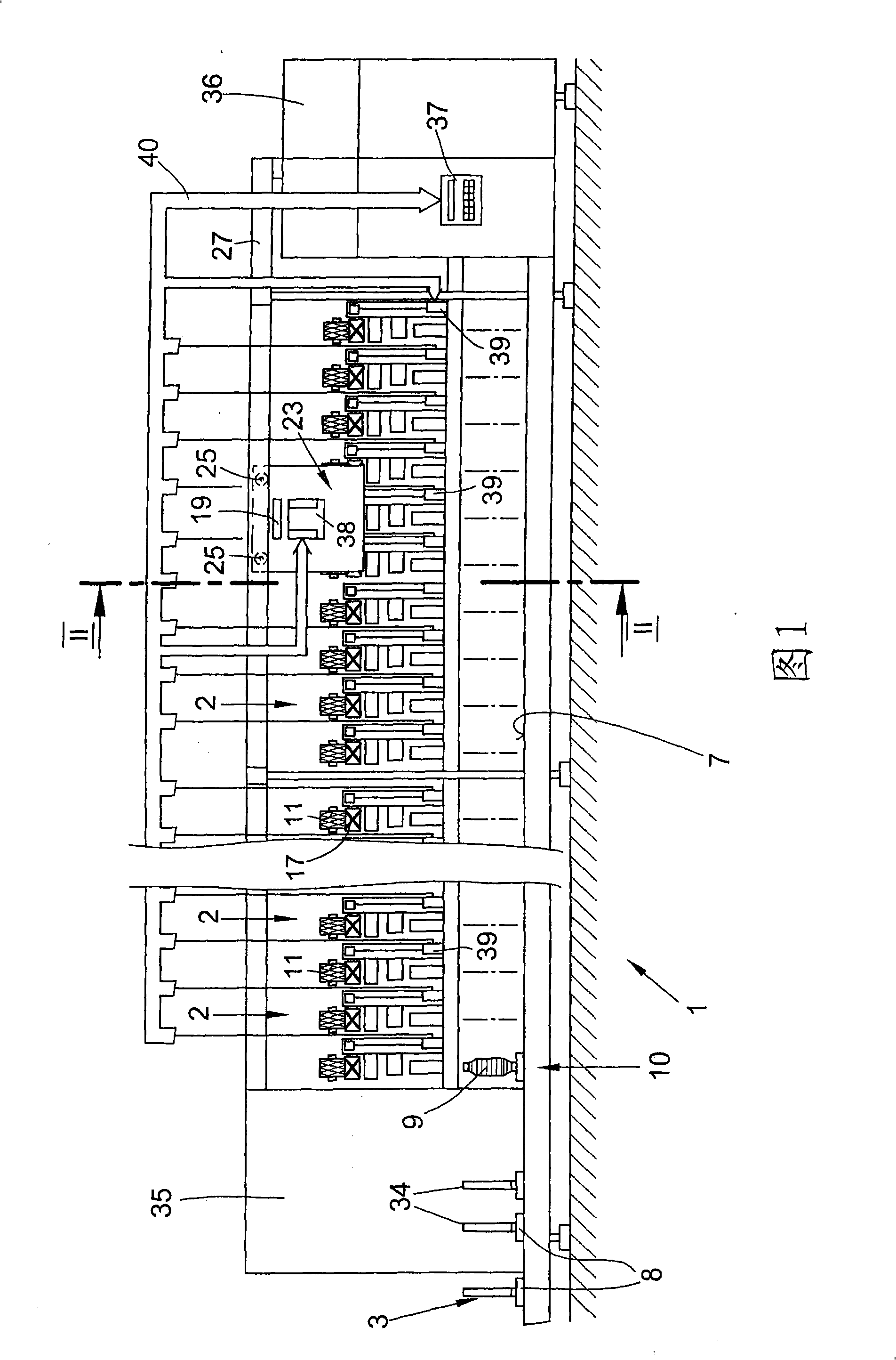
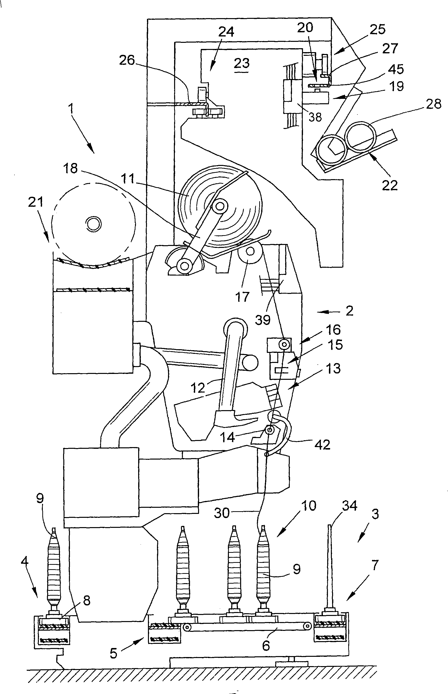
[0016] FIG. 1 schematically shows a front view of a textile machine for producing cross-wound bobbins. In this embodiment, the textile machine is an automatic cross-winder 1. This type of automatic cross-winding machine 1 usually has a large number of similar stations 2 between their end frames 35, 36. In these stations, the ring spinning machine (not The bobbin 9 produced on the illustration) is re-wound to form a large-capacity cross-wound bobbin 11. The completed cross-wound bobbin 11 is conveyed to the special cross-wound bobbin conveying mechanism 21 for the textile machine by means of an automatically operating service component 23, preferably by means of a so-called cross-wound bobbin doffing machine, and is then transferred to the machine end. A bobbin loading station (not shown) or similar device at the

[0017] This type of automatic cross-winding machine 1 usually also has a logistics mechanism in the form of a bobbin conveying system 3 in which bobbins or empty bobbins...


PUM


Abstract

The present invention relates to a service assembly for self-actuating support of cross-wound bobbin producing textile machine. The service assembly has multiple similar workplaces, which are provided with numerous thread handling devices. A device (19) is provided for mechanically engaging the service assembly with a workplace. The engaging device has two movably arranged catch elements (43A,43B), which are arranged and controlled so that they slide consecutively in a catch opening (20), and in the process the service assembly (23) is located and catched at a workplace (a) requiring service, so as to accurately locate the service assembly at the catch position.

Description

technical field [0001] The invention relates to a service assembly according to the preamble of claim 1 for the automatic feeding of a textile machine for the production of cross-wound bobbins. Background technique [0002] Servicing assemblies for the automatic servicing of workstations of textile machines or similar textile machines producing cross-wound bobbins, and having a mechanism for mechanically locking them at the workstation requiring service, are known and described in numerous patent applications and in various There are detailed descriptions in other references. [0003] For example from DE 2117585 A a movable maintenance device is known which travels along the spinning stations of a ring spinning machine and has a snap-in mechanism whose mechanical positioning can be activated by an actuatable switching cam to target mode actuation. In this known snap-in mechanism, according to a first embodiment, a pivotably mounted positioning roller is provided which is p...

Claims


Application Information

Patent Timeline
IPC IPC(8): B65H67/04B65H54/06D01H9/00
CPCB65H2701/31D01H15/013B65H54/26B65H2402/64B65H2402/60
Inventor 斯特凡·本特尔
Owner SAURER GERMANY GMBH & CO KG
Why Eureka
Try Eureka