Eureka AIR delivers breakthrough ideas for toughest innovation challenges, trusted by R&D personnel around the world.

Piling machine elevating chain monitoring apparatus and piling machine using the apparatus

A technology for lifting chains and monitoring devices, applied in the field of stacking devices, can solve problems such as failure to replace in time, chain breaking accidents, and inability to fully satisfy operational safety, etc., and achieve the effect of convenient handling and accident avoidance.

Inactive Publication Date: 2009-04-15
HUNAN SANY PORT EQUIP
View PDF0 Cites 7 Cited by
  • Summary
  • Abstract
  • Description
  • Claims
  • Application Information

AI Technical Summary

Problems solved by technology

Such as: Foreign objects fall between the raceways of the gantry rollers, causing the rollers to be stuck in the raceways, causing the spreader to fail to run; due to misoperation, the mast is deformed after collision, causing the spreader to be stuck; after long-term use of the gantry Local deformation causes the spreader to be stuck; the slider between the masts is excessively worn and is not replaced in time, causing interference between the assembly and the mast after shaking; etc.
When the spreader or mast is stuck: if the oil cylinder moves up forcibly, the chain and the mast will be damaged; if the oil cylinder moves down at this time, the spreader or mast will suddenly loosen, resulting in impact and pulling break the chain and cause an accident
[0005] The second is the partial load of the chain or the force of a single chain
After chain unbalanced load or a single chain is stressed, it will accelerate the damage of the chain, or even break the chain, resulting in an accident
[0006] The above-mentioned unsafe factors are common in the operation process of the forklift, but because the movement status of the lifting chain cannot be monitored in real time, the existing forklift cannot give an early warning when the lifting system is running abnormally, so it cannot fully meet the requirements of operation safety

Method used


Image

  • Piling machine elevating chain monitoring apparatus and piling machine using the apparatus
  • Piling machine elevating chain monitoring apparatus and piling machine using the apparatus
  • Piling machine elevating chain monitoring apparatus and piling machine using the apparatus

Examples


Embodiment Construction

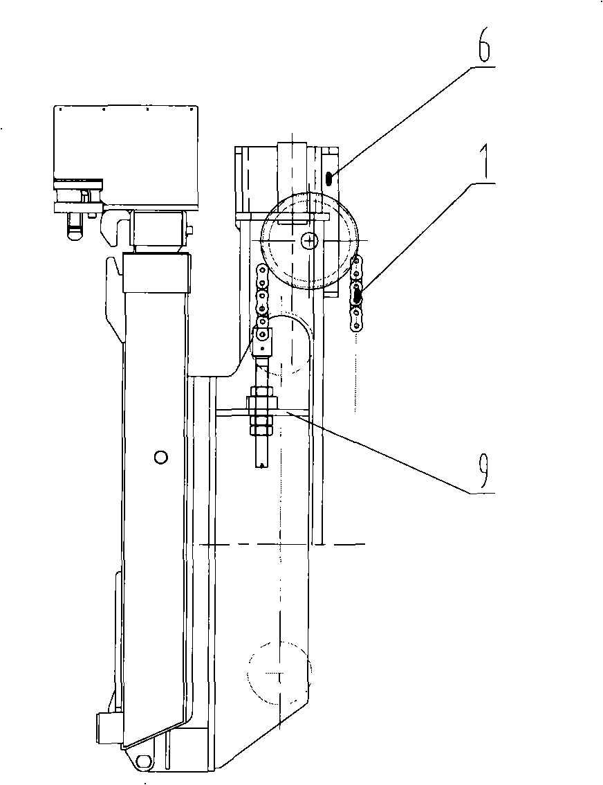
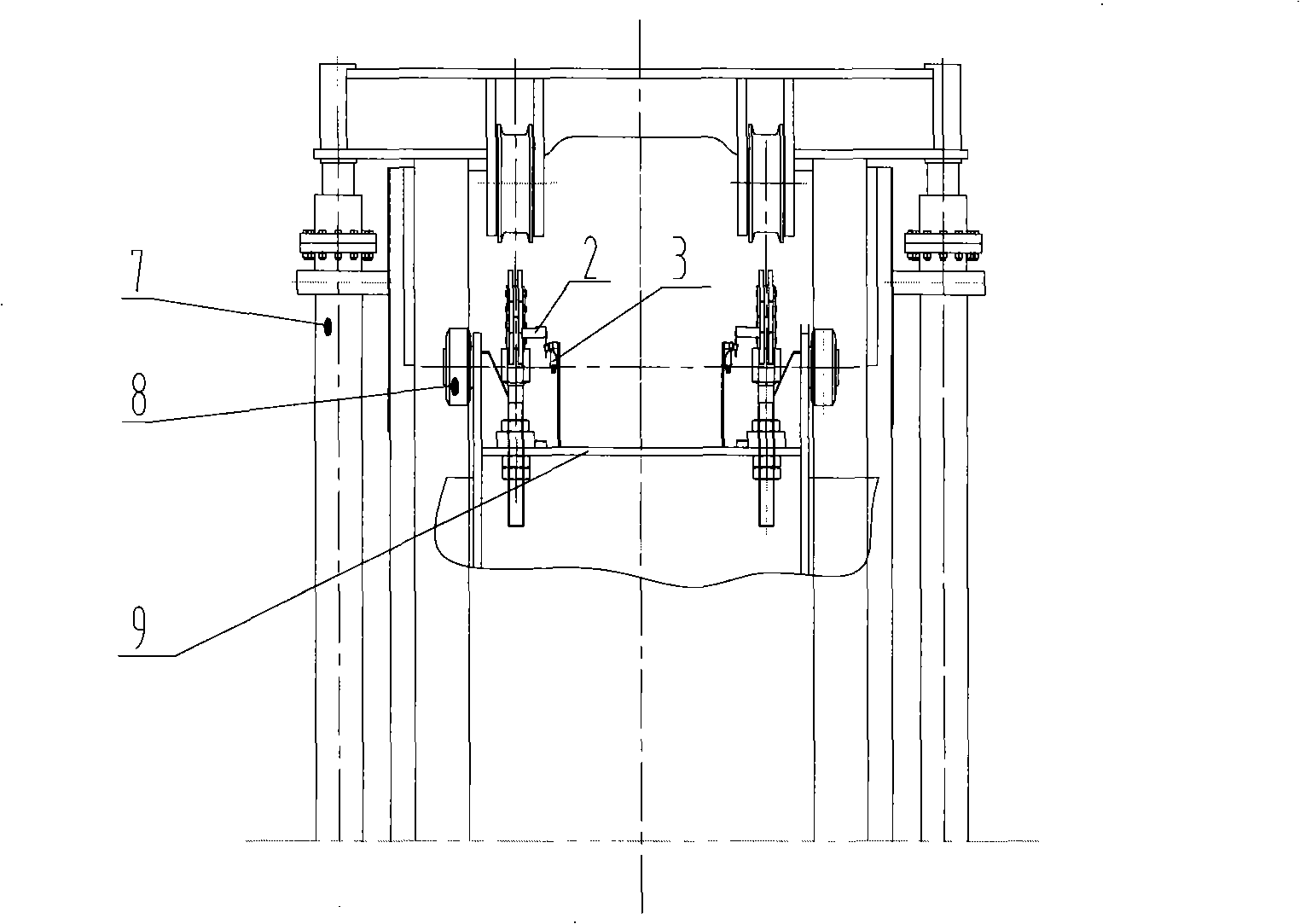
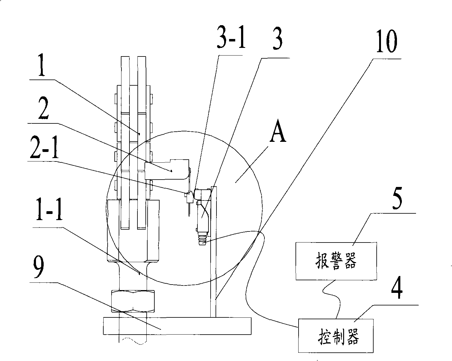
[0030] The basic concept of the present invention is that a trigger is set on the lifting chain, a trigger switch is set on the spreader, and the trigger switch is installed close to the trigger; when the lifting system of the stacker is abnormal, the trigger touches the trigger switch , so that the trigger switch triggers the alarm to alarm due to force.

[0031] The basic principle of the present invention is: the lifting power of the stacker is the oil cylinder, but the direct action mechanism is the chain, and the movement of the chain directly drives the operation of the spreader; at the same time, the chain is a flexible mechanism, and its characteristic is that it must be tensioned when it is stressed. Slack will not force. Therefore, by detecting the movement of the spreader chain in the mast, the operation status of the lift system of the forklift can be monitored in real time; thus, an alarm can be given when the lift system of the forklift is running abnormally to p...


PUM


Abstract

The invention discloses a monitoring device for the lifting chain of a stacking machine, which comprises a plurality of triggers which are respectively arranged on the corresponding lifting chain, a plurality of trigger switches which are respectively arranged on a hanger, and the probes of which press close to pressing parts of the triggers so as to send trigger signals when touching the pressing parts of the triggers, a controller which is connected with each trigger switch and used for sending alarm control signals when receiving the trigger signals, and a warner which is connected with the controller and used for sending alarm signals according to the alarm control signals. By the monitoring of the trigger switches to the triggers on the chains, the situations of abnormal shaking, looseness, and the like of the chain can be fedback to the complete machine through electrical signals to generate the alarm signals, thus being favorable to the in-time treatment of operators and avoiding the occurrence of failure. The invention also discloses the stacking machine using the monitoring device for the lifting chain of the stacking machine.

Description

technical field [0001] The invention relates to the field of stacking devices, in particular to a monitoring device for the lifting chain of a stacker and a stacker using the device. Background technique [0002] Container stacker (hereinafter referred to as stacker) is a container handling and stacking device, which belongs to walking lifting equipment in a certain sense. Because the forklift is a high-lift operation, its operation safety requirements are very high. However, the existing lifting system of the stacker adopts a lifting chain mechanism, and its operation safety is guaranteed by the mechanical structure, and it is difficult to play an early warning function when the operation is abnormal, which will be further explained below. [0003] Such as Figure 1A , Figure 1B The stacker lifting system shown includes: a door frame 6, which moves up and down through rollers 8; an oil cylinder 7, which provides the lifting power of the stacker; a spreader 9, which is in...

Claims


Application Information

Patent Timeline
IPC IPC(8): B66F9/07B66F9/20B66F17/00
Inventor 安旭波张寒李翠英
Owner HUNAN SANY PORT EQUIP
Why Eureka
Eureka Blog
Learn More