Check patentability & draft patents in minutes with Patsnap Eureka AI!

Stereo projection optical system

An optical system and stereoscopic projection technology, applied in the field of projection optical systems, can solve the problems of difficult movement, time-consuming, high cost and weight

Inactive Publication Date: 2009-04-15
HONG FU JIN PRECISION IND (SHENZHEN) CO LTD +1
View PDF0 Cites 6 Cited by
  • Summary
  • Abstract
  • Description
  • Claims
  • Application Information

AI Technical Summary

Problems solved by technology

While such systems are successfully used to form stereoscopic images, the cost and weight of the system is much higher than that of a single projector
Also, the optical alignment required for the two projectors is relatively difficult and time consuming
also, due to the weight and bulk of the two systems, it is extremely difficult to move such a system between the two locations, and there are potential image alignment issues

Method used


Image

  • Stereo projection optical system
  • Stereo projection optical system
  • Stereo projection optical system

Examples


Embodiment Construction

[0017] In order to further illustrate the present invention, the following preferred embodiments are given and described in detail with the accompanying drawings.

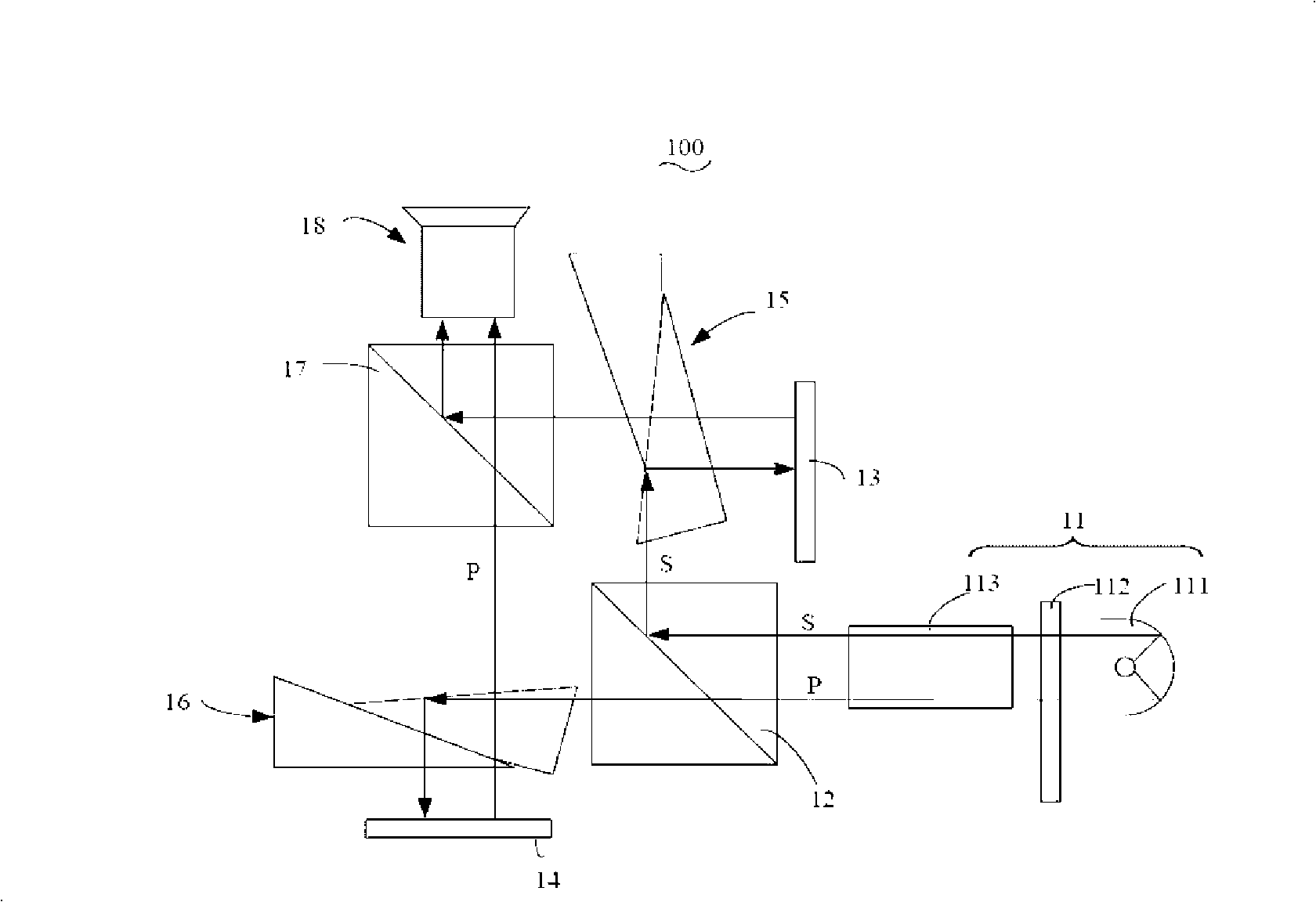
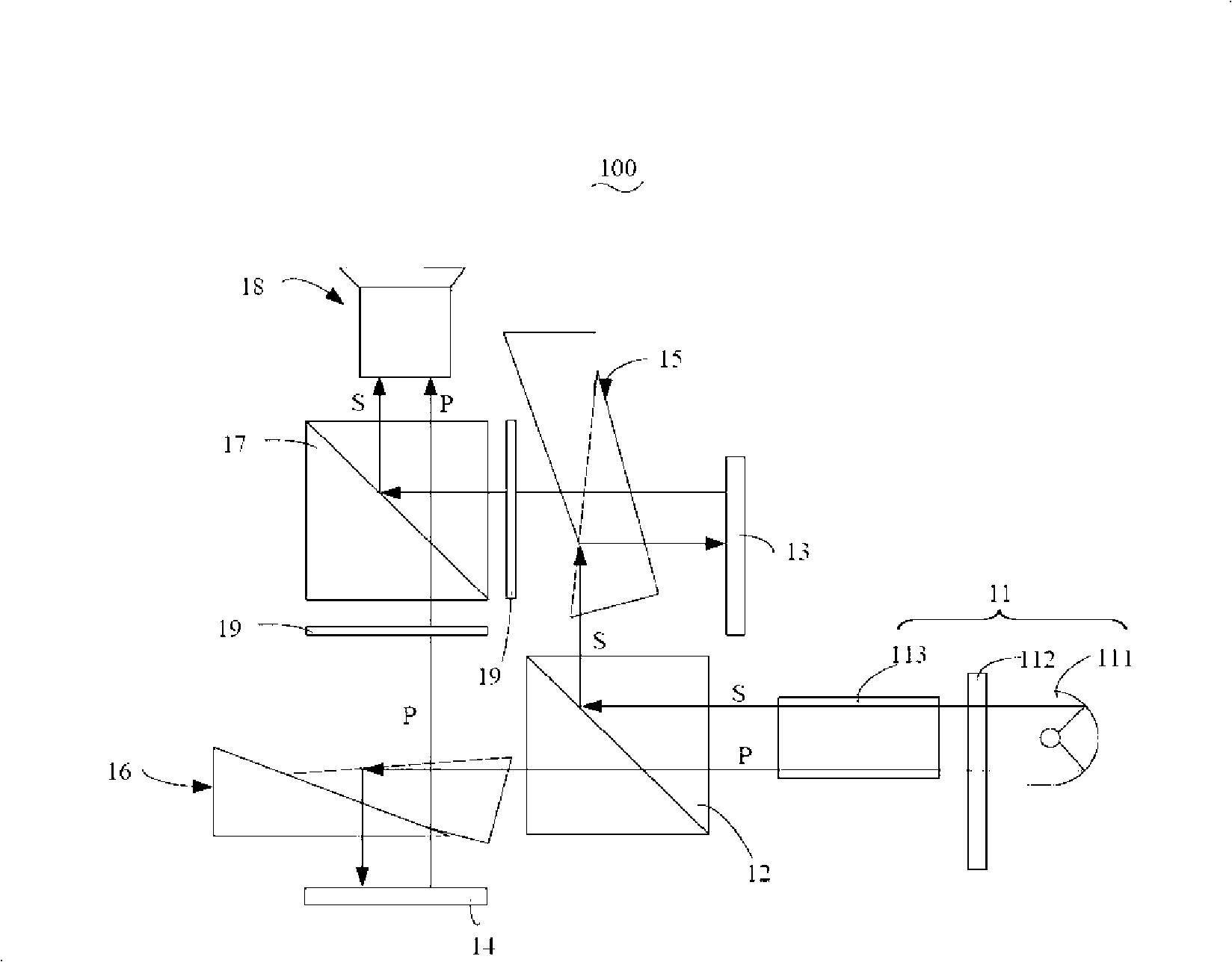
[0018] see figure 1 and figure 2 , is a schematic structural diagram of the stereoscopic projection optical system 100 according to the first embodiment of the present invention. The stereoscopic projection optical system 100 includes a light source assembly 11 , a polarization beam splitter 12 , a first digital micromirror element 13 and One for each of the second digital micromirror elements 14, one for each of the total internal reflection prisms 15, 16 respectively disposed between the first and second digital micromirror elements 13, 14 and the optical path of the polarizing beam splitter 12, one for each of the total internal reflection prisms 15, 16, one for each 1. Optical recombiners 17 on the outgoing optical paths of the second digital micromirror elements 13 and 14 and a projection lens 18 arranged o...


PUM


Abstract

The invention relates to a perspective projection optical system which comprises a polarized beam splitter, a first digital micro mirror element, a second digital micro mirror element, two total internal reflection prisms and a light recombiner; wherein, the polarized beam splitter is used for splitting an incident light into a first polarized light and a second polarized light; the first and second digital micro mirror elements are respectively arranged on the exit path of the first polarized and second polarized light; the two total internal reflection prisms are respectively arranged between the first digital micro mirror element and the light path of the polarized beam splitter as well as between the second digital micro mirror element and the light path of the polarized beam splitter; and the recombiner is arranged on the light path of the exit light of the first and second digital micro mirror elements and used for combining the incident light which arrives at the light recombiner, so as to form a projection beam. The perspective projection optical system forms two images by the first and second micro mirror elements and projects the two images by passing a projection lens by the first polarized light and the second polarized light respectively, so that a looker can watch perspective image information by wearing two analyzers which are vertical along the analyzing direction on the left and right eyes respectively.

Description

technical field [0001] The present invention relates to a projection optical system, in particular to a stereoscopic projection optical system with a stereoscopic projection display function. Background technique [0002] In recent years, image projectors, especially digital projectors, have become popular as tools for displaying various information to viewers. Typically, these projectors are used to project images generated by a computer onto a screen. To the viewer, the image projected by the image projector usually appears to be a flat two-dimensional image, which cannot display any image depth information other than the image itself. This display can be adapted to display a variety of information. However, in some cases, viewers desire a projector that can display the depth of field or structural features of an image to a greater extent than a two-dimensional display. [0003] One way of enabling images displayed in two dimensions to give the image depth of field is b...

Claims


Application Information

Patent Timeline
IPC IPC(8): G02B27/26G02B27/28H04N13/00G02B30/25
Inventor 简义本林信力林光伟赖柏元
Owner HONG FU JIN PRECISION IND (SHENZHEN) CO LTD
Features
  • R&D
  • Intellectual Property
  • Life Sciences
  • Materials
  • Tech Scout
  • Unparalleled Data Quality
  • Higher Quality Content
  • 60% Fewer Hallucinations
Learn More