Driving device of stepping motor

A technology of stepping motor and driving device, applied in the direction of motor generator control, electrical components, control system, etc., can solve the problems of excessive heating of the coil, inability to reduce the proportion of current flowing, and inability to sufficiently reduce power consumption, etc. Achieving the effect of reducing power consumption and high energy efficiency

Inactive Publication Date: 2009-04-15
JUKI CORP
View PDF0 Cites 8 Cited by
  • Summary
  • Abstract
  • Description
  • Claims
  • Application Information

AI Technical Summary

Problems solved by technology

Therefore, the ratio of the current flowing from the power supply device to the coil cannot be reduced, and there is a problem that the power consumption cannot be sufficiently reduced even when the stepping motor 100 is stopped.
Therefore, even when the stepping motor 100 is stopped, there is a problem that the coils 104, 105 generate too much heat.

Method used


Image

  • Driving device of stepping motor
  • Driving device of stepping motor
  • Driving device of stepping motor

Examples


Embodiment Construction

[0032] (Overall structure of the driving device of the stepping motor of the present invention)

[0033] Hereinafter, embodiments of the present invention will be described in detail with reference to the drawings.

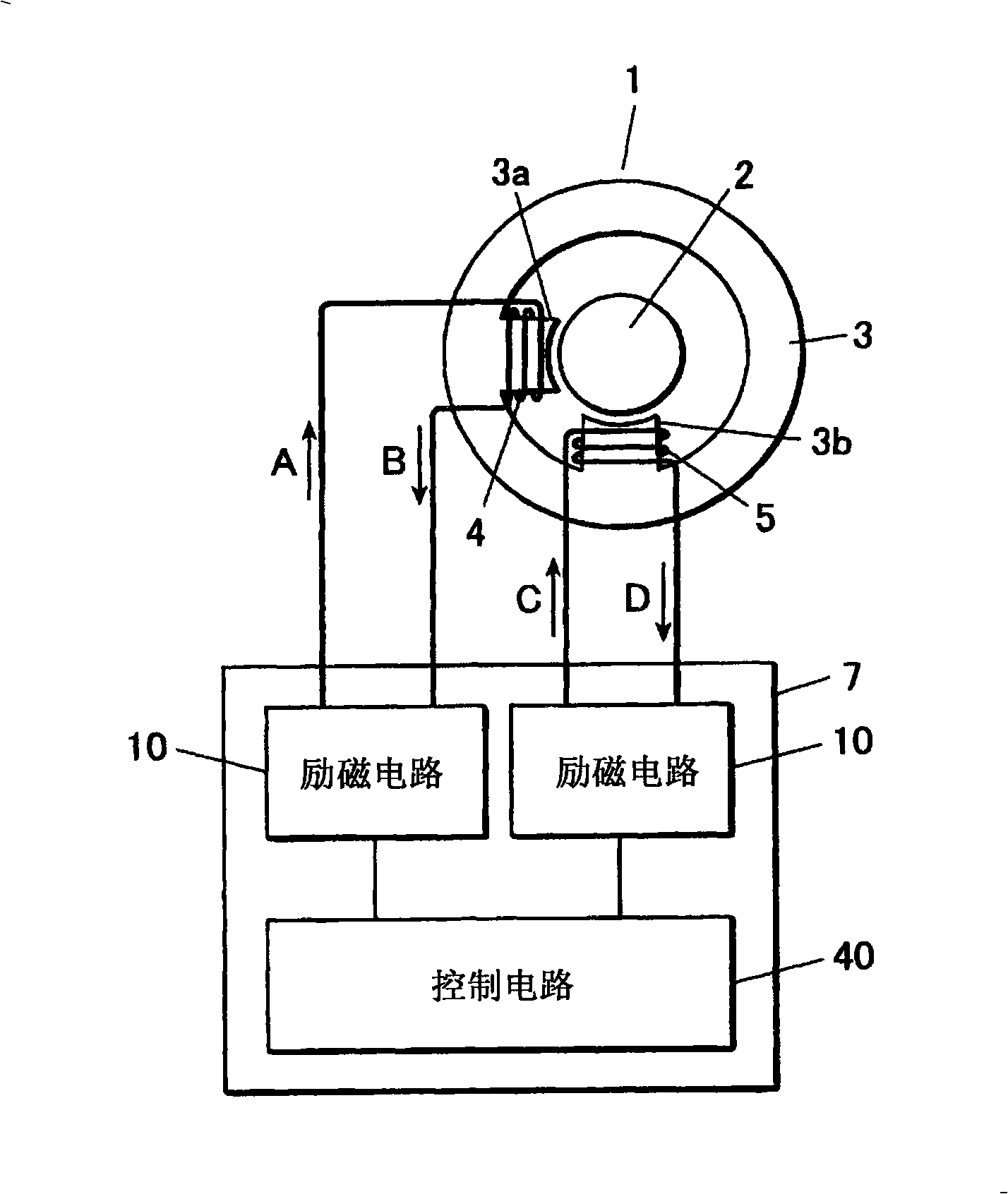
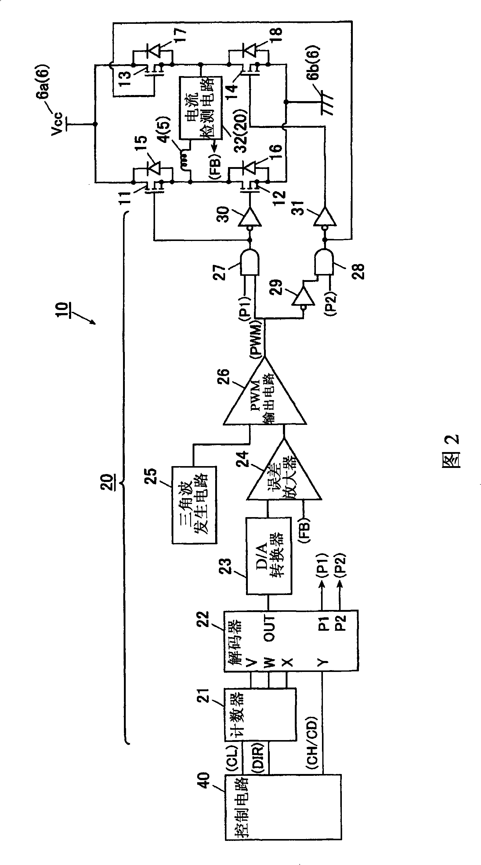
[0034] The driving device 7 of the stepping motor of the present invention is the driving device of the stepping motor of the sewing machine, and it has: FET (field effect transistor) 11~14, and it is arranged on the coil 4,5 of stepping motor 1 (refer to figure 1 ) between the power supply and function as a switching element (refer to FIG. 2 ); and the drive circuit 20 controls the current flowing in the coils 4 and 5 to a constant current by controlling the on / off of the FETs 11-14 ( Refer to Figure 2).

[0035] (stepping motor)

[0036] exist figure 1 Among them, the stepping motor 1 has: a cylindrical rotor 2, which is connected to the rotating shaft of the stepping motor so as to be rotatable; a cylindrical stator 3, which is arranged around the rotor 2;...


PUM


Abstract

The present invention provides a stepping motor drive device, which has high efficiency as a drive device of a stepping motor of a sewing machine. The drive device (7) of the stepping motor includes: an H-bridge circuit, which has FET (11-14) connecting coils (4, 5) with a power supply unit (6); as well as a drive circuit (20), controlling the current flowing through the coils (4, 5) by controlling the switching on / off of the FET (11-14). The drive circuit 20 makes the current generated by the self-induction of the coils (4, 5) returns back to the coils themselves when the stepping motor (1) stops.

Description

technical field [0001] The invention relates to a driving device for a stepping motor. Background technique [0002] Currently, stepping motors are classified into several types according to their structures, and there is known a two-phase stepping motor that normally drives two coils by exciting them with different excitation timings. [0003] exist Figure 13 , Figure 14 , Figure 15 In the following, a stepping motor 100 as a prior art will be described. [0004] The stepping motor 100 includes a rotor 102 made of a magnetic body such as a permanent magnet and supported rotatably, and two coils 104 and 105 provided near the outer periphery of the rotor 102 . Coils 104, 105 use a drive circuit not shown in the figure to flow in and Figure 14 The current corresponding to the excitation method shown in (a) is excited, and the rotation angle of the stepping motor 100 is controlled by causing the rotor 102 to rotate at a rotation angle corresponding to the excitation met...

Claims


Application Information

Patent Timeline
Patent Type & Authority Applications(China)
IPC IPC(8): H02P8/12
CPCH02P8/24
Inventor 立川修稻田昭夫
Owner JUKI CORP
Why Eureka
Try Eureka