
Optical disc device and record control method

An optical disc device, optical disc recording technology, applied in optical recording/reproducing/erasing methods, optical recording systems, disc-shaped record carriers, etc. The effect of eliminating time-lost, high-speed and reliable data logging

Inactive Publication Date: 2014-06-18
SONY CORP
View PDF7 Cites 0 Cited by
  • Summary
  • Abstract
  • Description
  • Claims
  • Application Information

AI Technical Summary

Problems solved by technology

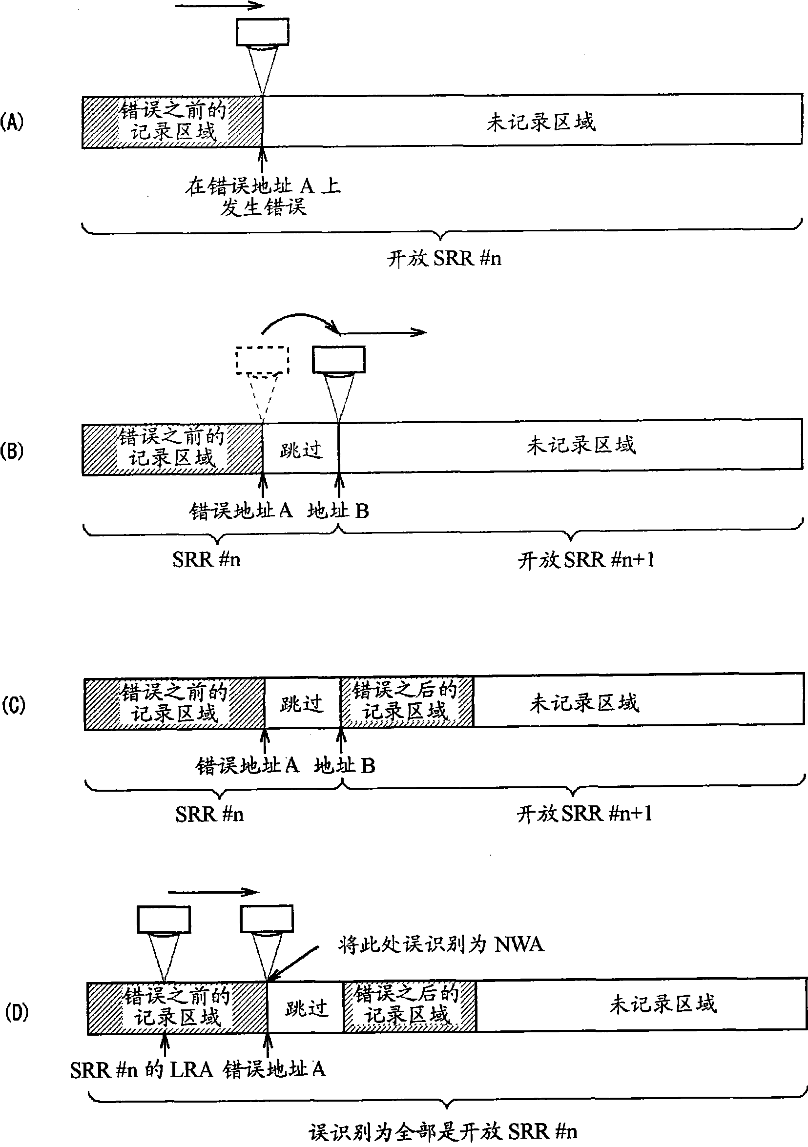
In this case, there is a problem that although the stream data being recorded is as Figure 8 It continues before and after the error occurrence as shown in (C), but the recording error may occur again due to the cause of the recording error (disc failure, etc.).
However, as described above, there is a problem that since the TDMS is provided in the writing area of ​​the inner periphery of the magnetic disk, when the division of the SRR and the update of the corresponding SRRI are performed according to the occurrence of a recording error, the optical disk device needs to be After the optical pickup moves from the recording track to the writing area to update the TDMS, the optical pickup returns to the recording track and restarts recording. Due to the time loss caused by the reciprocation of the optical pickup, It may not be possible to record streaming data in real time

Method used


Image

  • Optical disc device and record control method
  • Optical disc device and record control method
  • Optical disc device and record control method

Examples


Embodiment

[0031] (1) Overall structure of the optical disc device

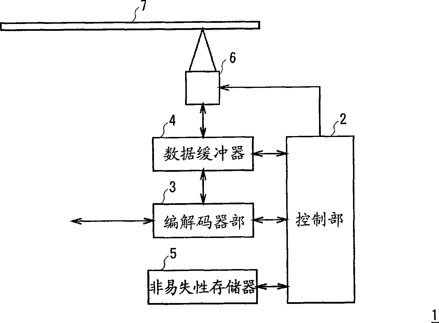
[0032] exist figure 1 Among them, 1 represents an optical disc device corresponding to a Blu-ray Disc to which the present invention is applied as a whole, and the codec unit 3, data buffer 4, and nonvolatile memory 5 are connected to a control unit 2 that controls the entire device to constitute the unit. CD device.

[0033] When the optical disc device 1 records video on an optical disc 7 composed of a Blu-ray disc, the codec unit 3 encodes video signals supplied from the outside in real time to generate stream data, and temporarily stores the stream data in the data buffer 4 , and provided to the optical pickup 6.

[0034] The optical pickup 6 drives a laser diode (not shown) based on the supplied stream data, and irradiates a light beam to the optical disc 7 to record the stream data. At this time, the control unit 2 controls a slide drive mechanism (not shown) so that the laser light emitted from the optical pi...


PUM


Abstract

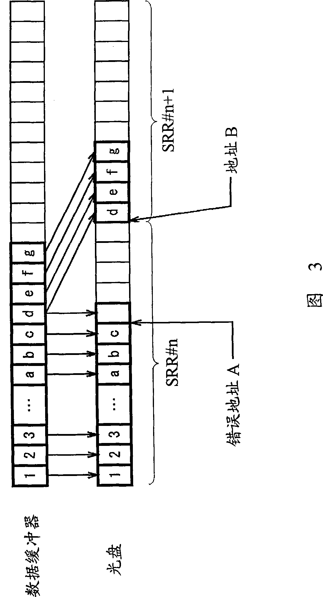
Data can be recorded on an optical disc at high speed and assuredly even in a case in which a recording error has occurred. In a case in which a recording error regarding data on the optical disc is detected, recording of the data is restarted avoiding recording in a predetermined range starting from an address at which the recording error has occurred, and also a recording area in which recording of the data is restarted is separated from a recording area including the address at which the recording error has occurred. When recording of the data on the optical disc is completed, information the recording area has been split is recorded in a management area on the optical disc.

Description

technical field [0001] The present invention relates to an optical disc device and a recording control method, which are suitable for use when recording data on an optical disc. Background technique [0002] In the past, rewritable (rewritable / -RW type) and recordable (write-once (write-once) / -R type) optical discs that allow users to freely record data have been widely used. disc drive. [0003] In addition, for the purpose of further increasing the recording capacity, a blue laser (wavelength 405nm) with a shorter wavelength than conventional CD (Compact Disc: Compact Disc) and DVD (Digital Versatile Disc: Digital Video Disc) has been developed. ) (Blu-ray Disc) (registered trademark of Sony Corporation), which also includes rewritable BD-RE and recordable BD-R (for example, refer to patent application 2006-024287) . [0004] In addition, in recent years, in video recording devices such as stationary video recorders and video handy cameras, it has become common to recor...

Claims


Application Information

Patent Timeline
Patent Type & Authority Patents(China)
IPC IPC(8): G11B20/12G11B7/0045G11B20/18
CPCG11B20/18G11B27/11G11B2220/2537G11B2220/20G11B2020/1896G11B2220/2541G11B2220/218G11B2020/10972G11B2020/1873G11B20/1883G11B7/0045G11B7/007G11B20/10
Inventor 赖本贤治加里本誉司四方英人古川睦伊藤直也大石力竹村真一伊藤智行久野启山本正晃
Owner SONY CORP
Learn More