Stacked type battery

A stack type, battery technology, applied in secondary batteries, large flat batteries/batteries, secondary battery manufacturing, etc., can solve the problems of increased manufacturing cost, increased size of deposition equipment, complicated management, etc., and achieves no drop in productivity , the effect of heat dissipation improvement

Inactive Publication Date: 2009-04-22
TOYOTA JIDOSHA KK
View PDF4 Cites 99 Cited by
  • Summary
  • Abstract
  • Description
  • Claims
  • Application Information

AI Technical Summary

Problems solved by technology

In this way, due to the cooling fins, the stiffness and ease of handling of the charge collector may be reduced, or the size of the deposition device may increase
Also, if there are different types of cooling fins, their management becomes complicated, or the manufacturing cost increases with more types of charge collectors

Method used


Image

  • Stacked type battery
  • Stacked type battery
  • Stacked type battery

Examples


Embodiment Construction

[0030] Embodiments of the present invention will be described with reference to the drawings. In the drawings referred to below, the same or corresponding members are denoted by the same reference numerals.

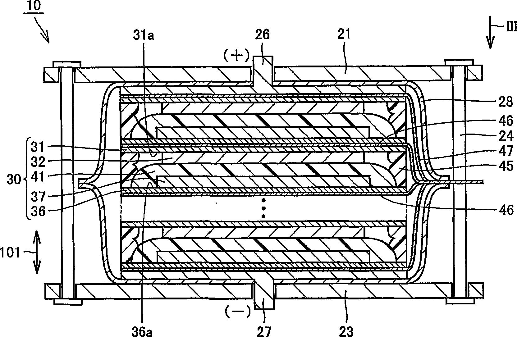
[0031] figure 1 It is a cross-sectional view showing a stacked battery in one embodiment of the present invention. refer to figure 1 , the laminated battery 10 is installed as a power source in a hybrid vehicle including an internal combustion engine (such as a gasoline engine or a diesel engine) and a rechargeable power source as a motive power source. The laminated battery 10 is formed of a lithium ion battery.

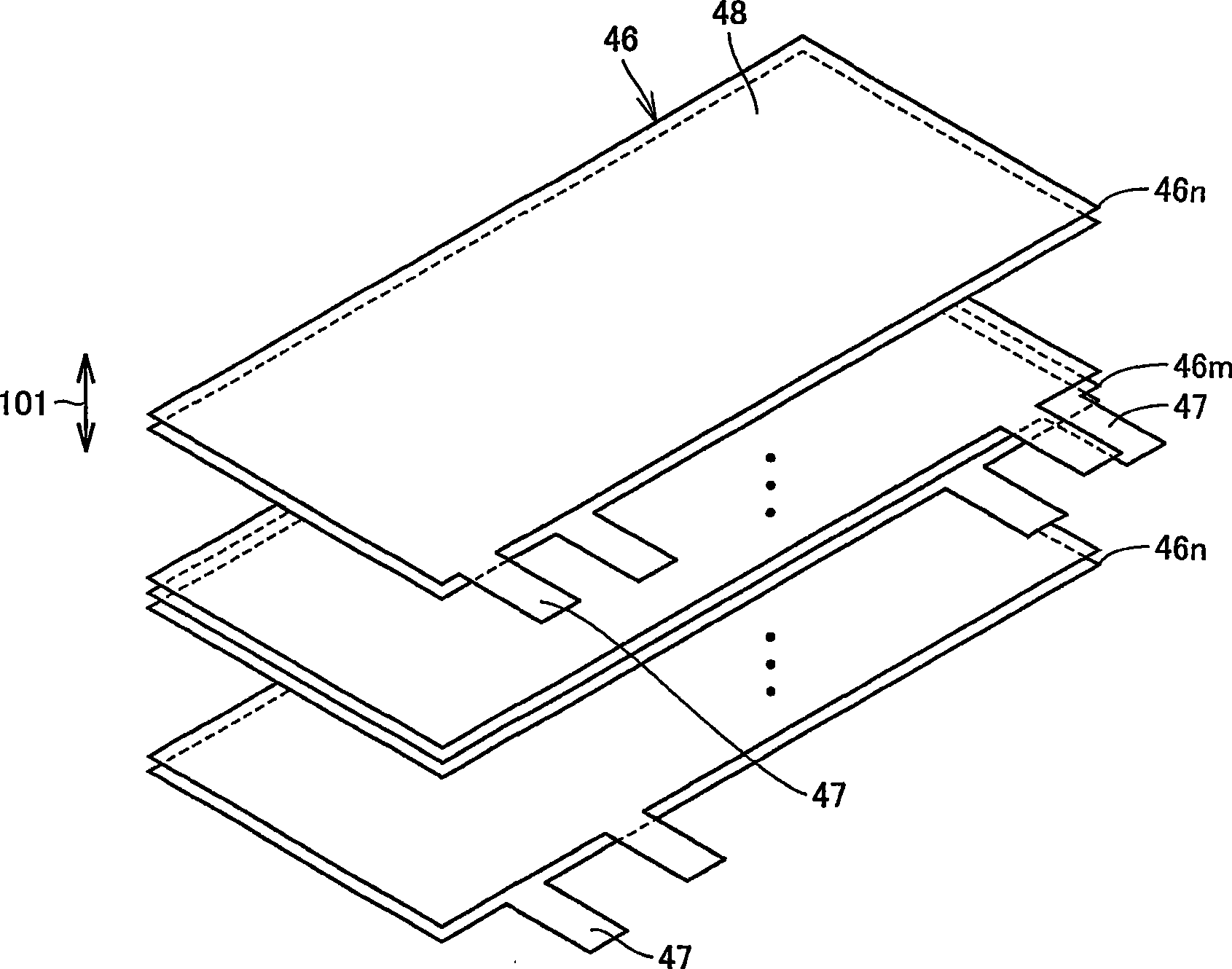
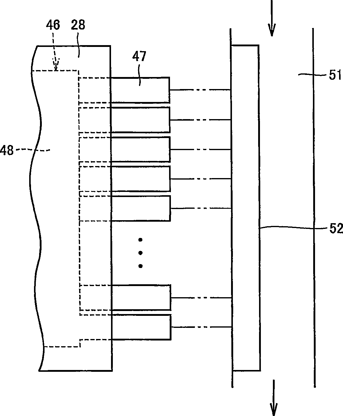
[0032] The laminated battery 10 includes a plurality of unit cells 30 stacked in a direction indicated by an arrow 101 and a plate member 46 arranged between the plurality of unit cells 30 . The laminated battery 10 has a substantially rectangular parallelepiped shape. The laminated battery 10 may have a flat shape in which the length in the stacking direc...


PUM


Abstract

A stacked cell (10) is provided with a plurality of stacked unit cells (30), which have a positive electrode collector foil (31) and a negative electrode collector foil (36); and a sheet member (46), which is arranged between the adjacent unit cells (30) and sandwiched between the positive electrode collector foil (31) and the negative electrode collector foil (36). The positive collector foil (31) and the negative collector foil (36) are provided with a positive electrode active material layer (32) and a negative active material layer (37), respectively. The positive electrode collector foil (31) and the negative electrode collector foil (36) are laid one over another to have the positive electrode active material layer (32) and the negative electrode material layer (37) face each other through an electrolyte layer (41). The sheet member (46) has a cooling tab (47) which extends from between the positive electrode collector foil (31) and the negative electrode collector foil (36). Thus, the stacked cell having improved heat dissipation is provided without deteriorating productivity.

Description

technical field [0001] The present invention relates to a laminated battery. Background technique [0002] As for conventional laminated batteries, for example, Japanese Patent Laid-Open No. 2005-71784 discloses a bipolar battery aimed at improving battery characteristics (Patent Document 1). In Patent Document 1, an electrode laminate forming a bipolar battery has a charge collector having a positive electrode active material layer formed on the front and a negative electrode active material layer formed on the back. The cooling fins are connected to the charge collectors. The cooling fin is independently attached to the charge collector, or is formed by extending a portion of the charge collector to the outside of the laminated battery. [0003] In addition, Japanese Patent Laid-Open No. 2004-31281 discloses a cooling structure of an electrode stack type battery for the purpose of preventing an increase in parts while compressing the battery from opposite sides and impro...

Claims


Application Information

Patent Timeline
Patent Type & Authority Applications(China)
IPC IPC(8): H01M10/04H01M10/50H01M10/613H01M10/05H01M10/0585H01M10/60H01M10/617H01M10/625H01M10/647H01M10/651H01M10/653H01M10/654H01M10/6551H01M10/6555H01M10/6556H01M10/6563
CPCY02E60/12H01M10/5042H01M10/5046H01M10/5004H01M10/0413H01M10/5055H01M10/5067H01M10/6563H01M10/654H01M10/6551H01M10/6555H01M10/613Y02E60/10Y02P70/50
Inventor 木村健治
Owner TOYOTA JIDOSHA KK
Why Eureka
Try Eureka