Glass severing device and method

A cutting device and glass technology, applied in glass cutting devices, glass production, identification devices, etc., can solve the problems of time-consuming, unable to cool glass plates, etc., and achieve the effect of increasing cutting speed and stabilizing formation

Inactive Publication Date: 2009-04-29
OMRON LASERFRONT INC
View PDF0 Cites 6 Cited by
  • Summary
  • Abstract
  • Description
  • Claims
  • Application Information

AI Technical Summary

Problems solved by technology

As described above, when using a cooling material such as water to control the elongation of cracks, it takes a lot of time to deal with the water, and when two glass plates are overlapped and cut, there is a problem that the glass plate arranged on the lower side cannot be cooled.

Method used


Image

  • Glass severing device and method
  • Glass severing device and method
  • Glass severing device and method

Examples


Embodiment Construction

[0020] Next, preferred embodiments for carrying out the glass cutting device and method of the present invention will be described with reference to the drawings.

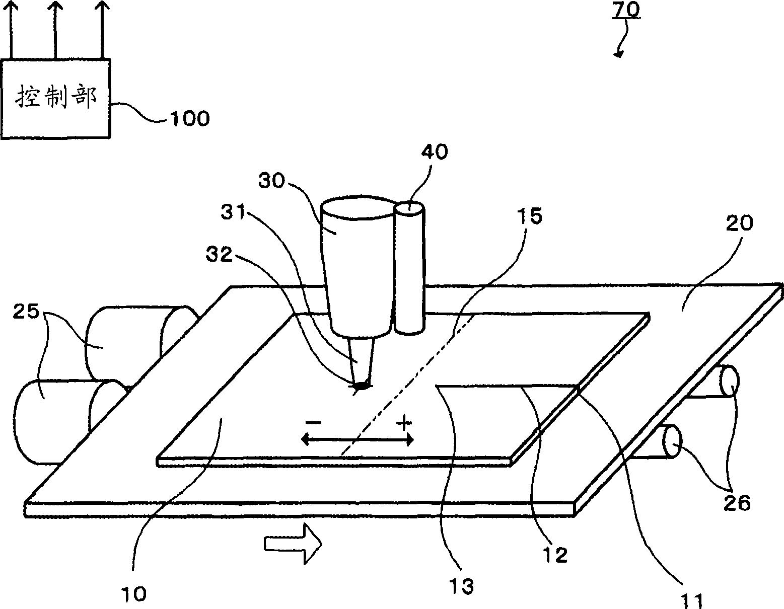
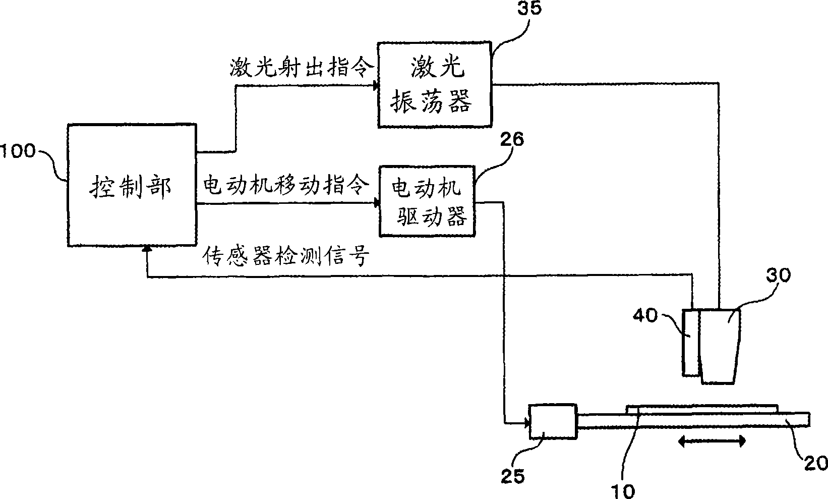
[0021] figure 1 It is a schematic diagram which shows the glass cutting apparatus and method of embodiment of this invention. This glass cutting device 70 has a placement plate 20 , a placement plate motor 25 , a ball screw 26 , a laser emitting unit 30 , and a sensor 40 .

[0022] The mounting plate 20 on which the glass plate 10 is placed has two nuts not shown below, and each nut is similarly connected to a ball screw 26 arranged below. A mounting plate motor 25 is connected to one end of the ball screw 26, and the mounting plate motor 25 can rotate the ball screw 26 in any direction. Arbitrary rotation of the placing plate motor 25 enables the placing plate 20 to move in an arbitrary uniaxial direction (left-right direction) along the arrows in the figure. In addition, the method of moving the placing board...


PUM


Abstract

This invention refers to a glass cutting device and method. The glass cutting device includes a holding plate having a holding glass plate, a holding plate drive unit which make the holding plate move in a single axle direction, a laser oscillation part which makes the laser on the glass plate oscillate, a sensor which sense a slit of the glass plate formed by the laser. The holding plate drive unit determines the moving speed of the holding plate in the single axel direction based on the elongation degree of the slit sensed by the sensor. Therefore, the excellent cutting can be performed by controlling the slit formed on the glass plate.

Description

technical field [0001] The present invention relates to a glass cutting device and method, and more particularly to a glass cutting device and method capable of stably cutting a glass plate by controlling the elongation of cracks formed on a glass plate. Background technique [0002] In the manufacture of flat panel display panels such as liquid crystal display panels and plasma display panels, display elements and circuits are formed on a single glass substrate, and divided along predetermined dividing lines, thereby taking out a plurality of components from a single glass substrate. panel. The panel is formed by bonding a pair of glass substrates formed with metals such as electrodes with an adhesive or the like, and the laser cutting device is also used for cutting other brittle materials besides the glass bonded in this way. [0003] Figure 5 Indicates that an existing CO 2 Cutting method of laser glass. Scores are formed on the cutting start end portion 51 of the gl...

Claims


Application Information

Patent Timeline
Patent Type & Authority Applications(China)
IPC IPC(8): C03B33/02C03B33/09G02F1/1333G09F9/00
CPCC03B33/03C03B33/037C03B33/10Y02P40/57
Inventor 村山伸一
Owner OMRON LASERFRONT INC
Why Eureka
Try Eureka