Parallel flow heat exchanger and use

An exchanger, parallel flow technology, used in evaporators/condensers, lighting and heating equipment, refrigeration components, etc., can solve the problem of increasing the volume of parallel flow heat exchangers, uneven distribution of gas and liquid, and unsatisfactory effects, etc. It can improve the heat exchange efficiency, improve the heat exchange medium, and solve the problem of uneven distribution.

Inactive Publication Date: 2009-04-29
王磊
View PDF3 Cites 11 Cited by
  • Summary
  • Abstract
  • Description
  • Claims
  • Application Information

AI Technical Summary

Problems solved by technology

[0009] Although the above changes can partially achieve the problem of uniform distribution of fluid in stacked heat exchangers and parallel flow heat exchangers, the effect is still not very satisfactory
[0010] The present inventor found in the research process of the parallel flow heat exchanger that when the refrigerant flows in the bottom header of the parallel flow heat exchanger along the axial direction of the bottom header, the separation of gas and liquid due to the difference in kinetic energy and density The layers are much more serious than the stratification when the refrigerant flows axially along the bottom header in the top header of the heat exchanger, and after the gas and liquid are stratified, it will cause more serious uneven distribution of gas and liquid. This is a very headache problem in this industry all the time
[0011] In addition, the existing parallel-flow heat exchanger uses segmented flow channels for heat exchange. Since the volume of each segment of the flow channel is basically the same, it is also an important problem that causes uneven flow distribution.
[0012] In addition, the existing parallel flow heat exchangers all use side inlet and outlet, which increases the volume of the parallel flow heat exchanger and makes installation difficult

Method used


Image

  • Parallel flow heat exchanger and use
  • Parallel flow heat exchanger and use
  • Parallel flow heat exchanger and use

Examples


Embodiment 1

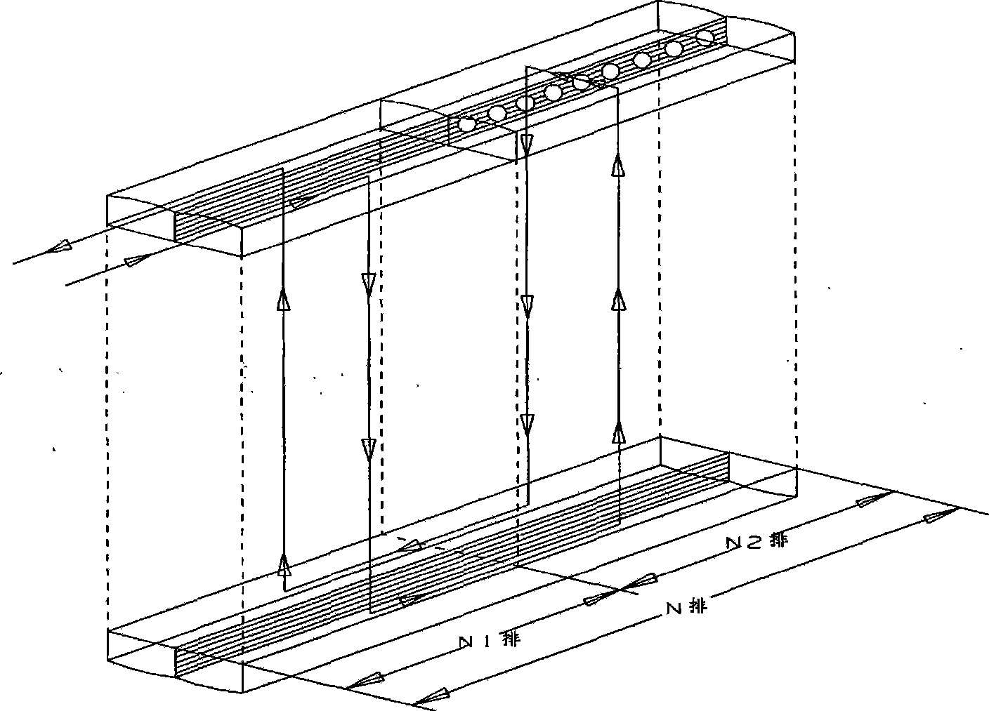
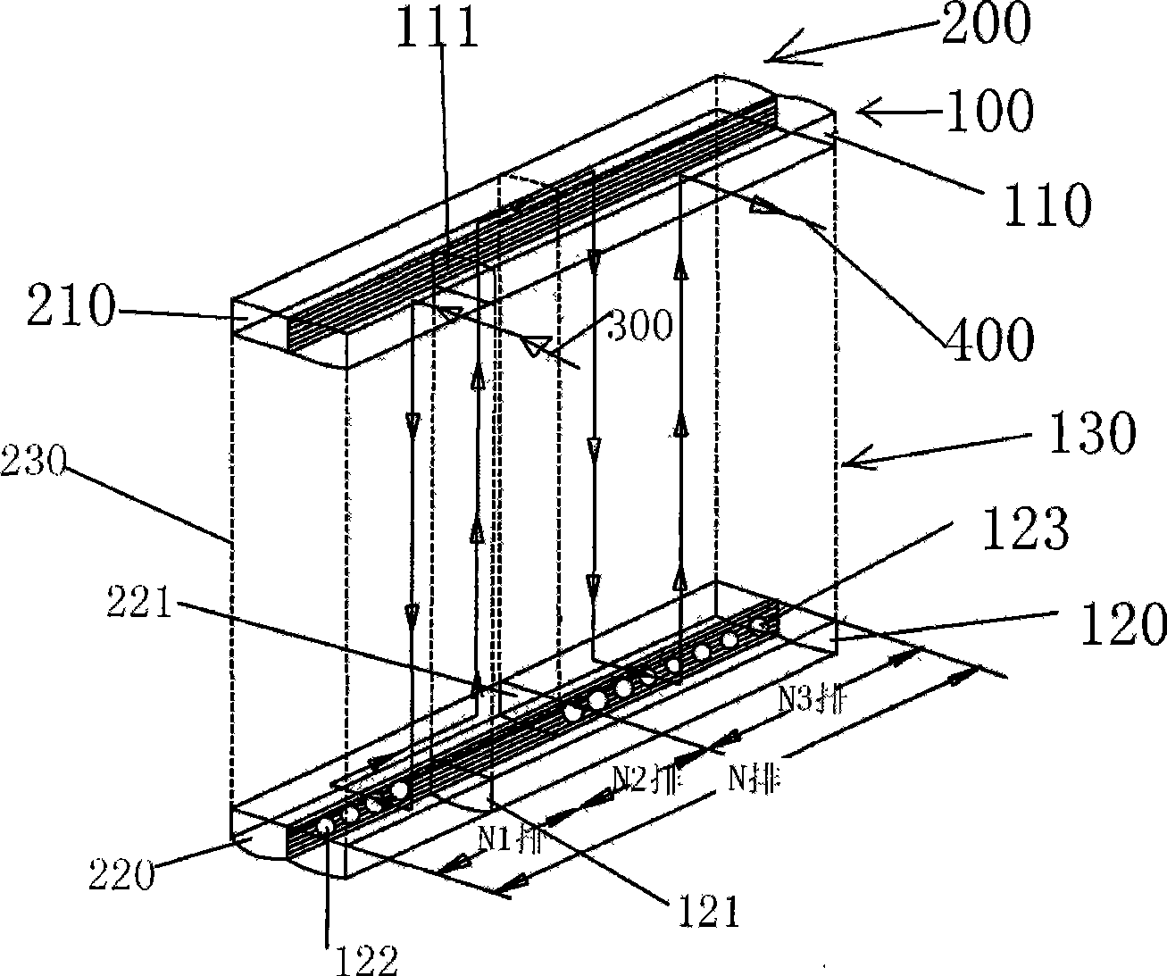
[0036] Such as image 3 The parallel flow heat exchanger shown is an evaporator used in an automobile. It includes two parallel flow heat exchanger units stacked together for ease of description and is defined as a first parallel flow heat exchange unit 100 and a second parallel flow heat exchange unit 200.

[0037] The first parallel flow heat exchange unit 100 includes a top header 110, a bottom header 120, and several parallel arranged flat tubes 130 connecting the top header 110 and the bottom header 120. The shape of the flat tubes 130 is the same as that of the present application. The Chinese invention patent "an aluminum extruded thin-wall profile" filed on April 21, 2006, has an application number of 200610025898.3 and an announcement number of CN1967135, which will not be described in detail here.

[0038] The second parallel flow heat exchange unit 200 includes a top header 210, a bottom header 220, and several parallelly arranged flat tubes 230 connecting the top header...

Embodiment 2

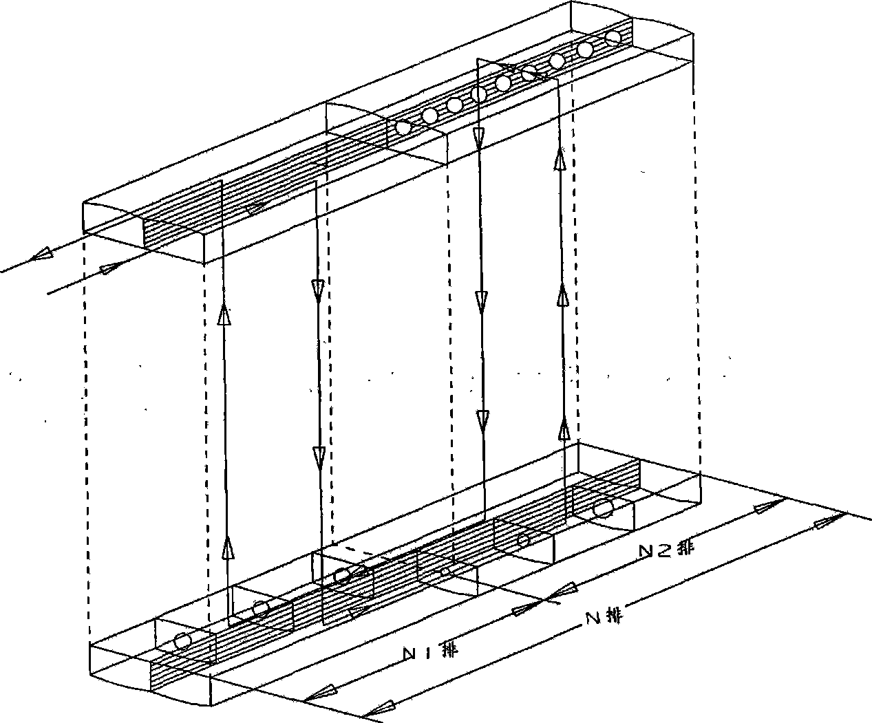
[0043] Such as Figure 4 The parallel flow heat exchanger shown is an evaporator used in an automobile. It includes two parallel flow heat exchanger units stacked together for ease of description and is defined as a first parallel flow heat exchange unit 100 and a second parallel flow heat exchange unit 200.

[0044] The first parallel flow heat exchange unit 100 includes a top header 110, a bottom header 120, and a plurality of parallel arranged flat tubes 130 connecting the top header 110 and the bottom header 120. The shape of the flat tubes 130 is the same as the embodiment. 1.

[0045] The second parallel flow heat exchange unit 200 includes a top header 210, a bottom header 220, a draft tube 240, and several parallel arranged flat tubes 230 and a flat tube 130 connecting the top header 210 and the bottom header 220. The shape is the same as in Example 1. The flat tubes 230 and 130 can be connected as a whole as described in the invention with the application number 200610025...

Embodiment 3

[0055] Such as Figure 5 Parallel flow heat exchanger shown. It includes three parallel flow heat exchanger units stacked together for ease of description, and is defined as a first parallel flow heat exchange unit 100, a second parallel flow heat exchange unit 200, and a third parallel flow heat exchange unit 500.

[0056] The first parallel flow heat exchange unit 100 includes a top header 110, a bottom header 120, and a plurality of parallel arranged flat tubes 130 connecting the top header 110 and the bottom header 120. The shape of the flat tubes 130 is the same as the embodiment. 1.

[0057] The second parallel flow heat exchange unit 200 includes a top header 210, a bottom header 220, and several parallelly arranged flat tubes 230 connecting the top header 210 and the bottom header 220. The shape of the flat tubes 230 is the same as the embodiment 1.

[0058] The third parallel flow heat exchange unit 500 includes a top header 510, a bottom header 520, and several parallel ...


PUM


Abstract

The invention relates to a parallel flow heat exchanger, which comprises at least two stacked parallel flow heat exchange units, wherein each parallel flow heat exchange unit comprises a top flow collecting pipe, a bottom flow collecting pipe, and a plurality of parallel flat pipes communicating the top flow collecting pipe and the bottom flow collecting pipe; and the axial flowing length of a heat exchange medium on the top flow collecting pipe is larger than that on the bottom flow collecting pipe; and the axial flowing length on the top flow collecting pipe is as long as possible, while the axial flowing length on the bottom flow collecting pipe is as short as possible. The parallel flow heat exchanger improves the heat exchange medium of two-phase flow of gas and liquid remarkably, in particular solves problem of delamination of the gas and the liquid in refrigerant, so as to effectively solve the problem of uneven distribution of the gas and the liquid, improve heat exchange efficiency of the heat exchanger, and fully evaporate the refrigerant. At the same time, the parallel flow heat exchanger saves volume and reduces cost.

Description

Technical field [0001] The invention relates to the technical field of heat exchanger flow channel design, in particular to a parallel flow heat exchanger adopting a gas / liquid two-phase flow in a multilayer parallel flow structure and its use. Background technique [0002] Heat exchangers currently used in evaporators and condensers are generally classified into stacked heat exchangers and parallel flow heat exchangers. The so-called stacked heat exchanger is composed of a plurality of stacked heat exchanger units, which can theoretically be stacked without limitation. However, a heat exchanger unit of one size of this type of laminated heat exchanger requires a set of molds to manufacture, and it takes about 1 million yuan to open such a set of molds. If the size of the heat exchanger unit is changed, additional mold manufacturing needs to be opened, resulting in increased investment. [0003] The so-called parallel flow heat exchanger is a combination of flat tubes and upper a...

Claims


Application Information

Patent Timeline
Patent Type & Authority Applications(China)
IPC IPC(8): F25B39/00F25B39/02
Inventor 王磊
Owner 王磊
Why Eureka
Try Eureka