Restoration device for liquid crystal device and driving method thereof

A liquid crystal display, over-driving technology, applied in static indicators, instruments, etc., can solve problems such as poor under-charge repair, over-charge repair, and difficult adjustment, and achieve the effect of avoiding over-charge or under-charge repair.

Active Publication Date: 2009-04-29
NANJING CEC PANDA LCD TECH
View PDF1 Cites 13 Cited by
  • Summary
  • Abstract
  • Description
  • Claims
  • Application Information

AI Technical Summary

Problems solved by technology

Therefore, in practical applications, when the above-mentioned overdrive repair line operational amplifier repairs the repair line, it is difficult to predict the overpotential time of repair, and two repair failure phenomena shown in Figure 4 may occur, namely, overcharge repair Poor fixes for bad and undercharged
[0006] In order to cope with the possible repair defects that may occur when the abo

Method used


Image

  • Restoration device for liquid crystal device and driving method thereof
  • Restoration device for liquid crystal device and driving method thereof
  • Restoration device for liquid crystal device and driving method thereof

Examples


Embodiment 1

[0035] Figure 6 It is a system architecture diagram of Embodiment 1 of the present invention.

[0036] See Figure 6 , the overdrive real-time adjustable device 16 in this embodiment includes a PWM (pulse width modulation) modulator and a modulating resistor, and the PWM modulator is provided with an input terminal connected to the modulating resistor, by adjusting the modulating resistor to adjust the output duty cycle of the PWM modulator. Input the preset control signal into the PWM modulator, the repetition period of the preset control signal is the pixel charging time TP, and the high level duration is the overpotential time T1; the preset control signal is adjusted by the PWM modulator, and the output adjustment control The signal is sent to the control signal input terminal of the overdrive repairing line operational amplifier 15; the repeat period of the adjustment control signal is also the pixel charging time TP, but the high level time is adjusted to the overpote...

Embodiment 2

[0038] Figure 7 It is a system architecture diagram of Embodiment 2 of the present invention.

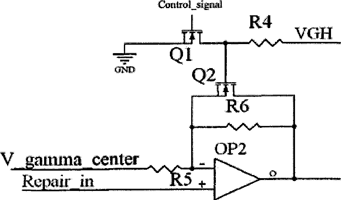
[0039] See Figure 7, the overdrive real-time adjustable device 16 in this embodiment includes: a first MOS transistor Q1, the gate of which is connected to a preset control signal, the drain is grounded, and the source is connected to a high-level potential through a first resistor R1; A resistor R1 and the source connection of the first MOS transistor Q1 are connected to the modulating terminal of the modulating resistor VR; any terminal of the modulating resistor VR except the modulating terminal is connected to the first capacitor C1; The other end of a capacitor C1 is connected to the gate of the second MOS transistor Q2; the drain of the second MOS transistor Q2 is grounded, and the source is connected to a high level voltage through the second resistor R2; between the second MOS transistor Q2 and the second The connection of the resistor R2 outputs the adjustment control s...


PUM


Abstract

The invention relates to a restoration device of an LCD and a driving method thereof; the restoration device comprises an overdrive operational amplifier which inputs reset control signal and data signal, when the reset control signal is in high level, overdrive signal is output; when the reset control signal is in low level, normal data signal is output; wherein, an overdrive time real time adjustable device which is used for regulating the lasting time of high level of the reset control signal is arranged in front of the operational amplifier. The restoration device of the LCD and the driving method thereof can correspondingly regulate restoration signals according to the position of broken wire on a panel and the lingering measurement of actual restoration wire RC, thus avoiding the poor restoration of over-charging and under charging.

Description

technical field [0001] The invention relates to a repairing device of a liquid crystal display and a driving method thereof, in particular to a repairing device and a driving method of a liquid crystal display capable of adjusting repairing signals on-line. Background technique [0002] A liquid crystal display (LCD) displays images by changing the orientation of the liquid crystal molecules to control the intensity of light transmission by changing the intensity of the electric field clamped on the liquid crystal molecules. At present, liquid crystal display devices have been widely used in various terminal display devices of large, medium and small sizes due to their characteristics of light weight, small volume, and thin thickness. Generally, a liquid crystal display device includes a liquid crystal display panel having a pixel matrix and a driving circuit for driving the liquid crystal display panel. [0003] Such as figure 1 As shown, the liquid crystal display device...

Claims


Application Information

Patent Timeline
IPC IPC(8): G09G3/36
Inventor 朱修剑
Owner NANJING CEC PANDA LCD TECH
Why Eureka
Try Eureka