Tensioner for an endless drive

A transmission device and tensioner technology, which is applied to transmission devices, belts/chains/gears, mechanical equipment, etc., can solve problems such as the complex structure of the tensioner, and achieve the effect of a compact structure

Active Publication Date: 2009-04-29
LITENS AUTOMOTIVE INC
View PDF1 Cites 15 Cited by
  • Summary
  • Abstract
  • Description
  • Claims
  • Application Information

AI Technical Summary

Problems solved by technology

But the structure of the tensioner is more complicated

Method used


Image

  • Tensioner for an endless drive
  • Tensioner for an endless drive
  • Tensioner for an endless drive

Examples


Embodiment Construction

[0031] In the following description of embodiments of the invention, the same elements are provided with the same reference numerals.

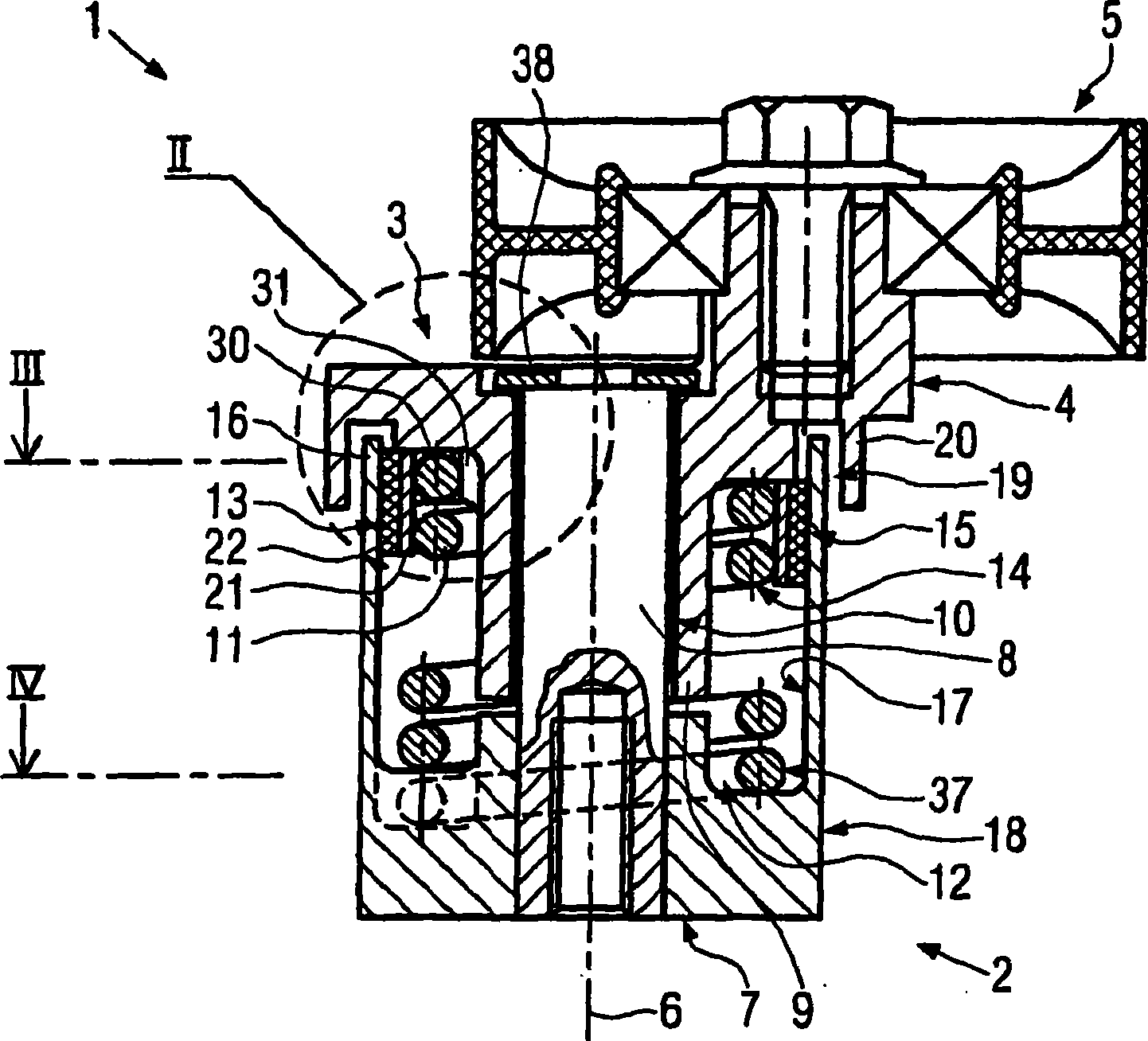
[0032] figure 1 A longitudinal sectional view of an embodiment of the tensioner 1 according to the invention is shown. The tensioner can tension an endless drive, in particular a belt drive of an internal combustion engine. The tensioner 1 has a base part 2 with which the tensioner can be fastened, for example, to an internal combustion engine, and a tensioner 3 with a tensioning arm 4 carrying tensioning rollers 5 . The tensioning element 3 is rotatable about an axis 6 relative to the base element 2 .

[0033] The base part 2 has an inner bush 7 , which in this embodiment of the invention is a bearing bush and is formed in one piece with the base part 2 . A bearing journal 8 is pressed into the bearing bush 7 . The tensioning element 3 has an inner bush 9 which in this embodiment of the invention is a rotary bushing 9 formed integrally w...


PUM


Abstract

The present invention relates to a tensioner (1) for an endless drive, in particular of an internal combustion engine, wherein the tensioner has a base part (2) and a clamping part (3) which can rotate relative to the former, a spring element (11) which is arranged between the base part and the clamping part (3) so as to impart a force, and a friction apparatus (12) which is provided between the spring element (11) and the base part or the clamping part (3) and by way of which the relative movement between the base part (2) and the clamping part (3) is damped. In order to improve a tensioner of the generic type in such a way that a simple construction is possible with satisfactory damping, it is proposed to arrange the friction apparatus (13) radially outside the spring element (11).

Description

technical field [0001] The invention relates to a tensioner for an endless drive, in particular for an internal combustion engine. Background technique [0002] A tensioner of this type is known from DE 40 10 928 A1. The tensioner has a base part with a friction bushing, inside which a sleeve of the tensioning element with a tensioning arm is rotatably mounted. A support bushing is provided between the sleeve and the friction bushing. [0003] The tensioning part is tensioned relative to the base part by means of a spring element designed as a helical spring which surrounds the friction lining. A spring bushing is provided between the coil spring and the friction bushing. If the tension member is rotated against the tensioning force of the spring element, the spring element is tightly contracted, whereupon the spring element is securely wound around the spring bushing. The spring bushing is thereby pressed firmly against the friction bushing. With the high friction thus...

Claims


Application Information

Patent Timeline
Patent Type & Authority Applications(China)
IPC IPC(8): F16H7/12F16H7/08
CPCF16H7/1281F16H7/1218F16H2007/081F16H7/08F16H7/12
Inventor 沃尔夫冈·古尔
Owner LITENS AUTOMOTIVE INC
Why Eureka
Try Eureka