
Light emitting diode module

A technology of light-emitting diodes and LED modules, which is applied to semiconductor devices of light-emitting elements, light sources, lighting and heating equipment, etc., can solve problems such as inaccurate detection and inaccurate LED output adjustment.

Inactive Publication Date: 2009-04-29
KONINKLIJKE PHILIPS ELECTRONICS NV
View PDF1 Cites 3 Cited by
  • Summary
  • Abstract
  • Description
  • Claims
  • Application Information

AI Technical Summary

Problems solved by technology

[0003] However, a drawback of the LED module in US6611000 is that the single photodetector is most sensitive to the LED closest to it, which can lead to inaccurate detection and subsequent inaccurate LED output regulation

Method used


Image

  • Light emitting diode module
  • Light emitting diode module
  • Light emitting diode module

Examples


Embodiment Construction

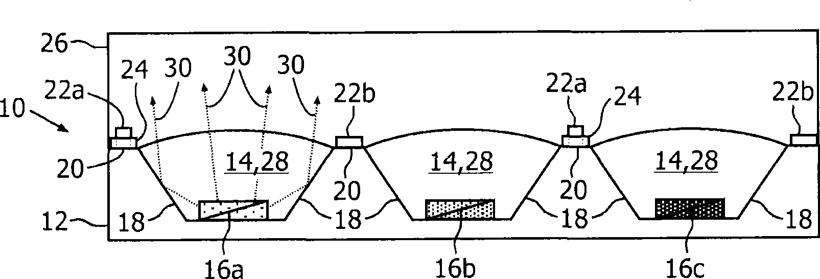
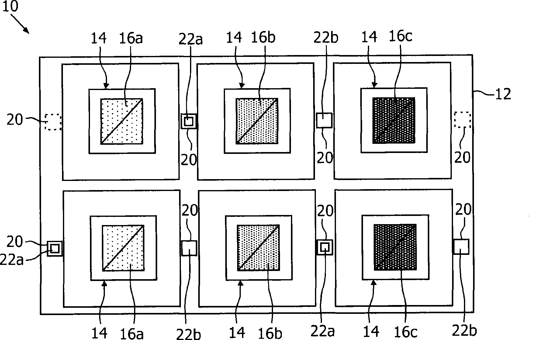
[0017] Figure 1a is a schematic cross-sectional side view of an LED module 10 according to an embodiment of the present invention. The LED module 10 includes a pre-etched substrate 12 with a plurality of recesses 14 . This recess 14 is preferably pre-etched. In each recess 14, LEDs generally indicated at 16 (in this case a red LED 16a, a green LED 16b, and a blue LED 16c) are provided. The LEDs may be intrinsic LEDs or phosphor converted LEDs. Each LED 16 is mounted on the bottom surface of the groove 14 . The groove 14 has inclined side surfaces 18 . Figure 1a The inclined side surfaces 18 in are planar, but alternatively they may be curved. The inclined side surfaces 18 and optionally the bottom surface of the groove 14 are preferably reflective, for example equipped with a reflective coating.

[0018] Between said grooves 14 , close to the outer grooves, substantially flat portions 20 are formed, on which a sensor generally indicated at 22 is mounted. Sensors 22 may ...


PUM


Abstract

The present invention relates to a light emitting diode (LED) module (10) comprising a substrate (12) having plural indents (14) and flattish portions (20) in between the indents, and LEDs (16) mounted in the indents. The LED module is characterized by at least one of sensors (22) and additional LEDs (32) provided at the flattish portions. This allows increased sensor detection accuracy and / or color compensation. The present invention also relates to a method for the manufacturing of such an LED module.

Description

technical field [0001] The present invention relates to a light emitting diode (LED) module comprising a substrate having a plurality of grooves and flat portions between the grooves, and LEDs installed in the grooves. The invention also relates to a method for producing such an LED module. Background technique [0002] An example of an LED module of the above-mentioned type is disclosed in document US6611000, wherein a plurality of grooves are formed on the substrate, each groove fitting an LED. All LEDs are the same color. A single photodetector is further mounted on the edge of the substrate, next to the groove and LED. Both the LED and the photodetector are covered with a transparent resin layer. The function of the single photodetector is to detect the light output emitted by the LED through the transparent resin layer and to feed the output back to the control and drive circuitry whereby in the event the detected output differs from the desired output The output of...

Claims


Application Information

Patent Timeline
Patent Type & Authority Applications(China)
IPC IPC(8): H01L25/075H01L33/00F21K99/00
CPCF21K9/00F21V23/0457H01L25/167H01L2924/0002H01L2924/00
Inventor L·王J·L·A·M·索马尼P·H·F·杜伦伯格E·J·梅杰
Owner KONINKLIJKE PHILIPS ELECTRONICS NV
Learn More