Vehicle lamp
A technology for vehicle lights and vehicles in front, which is applied to headlights, vehicle parts, lighting and heating equipment, etc., and can solve problems such as blinding, incoordination, and inability to eliminate
- Summary
- Abstract
- Description
- Claims
- Application Information
AI Technical Summary
Problems solved by technology
Method used
Image

Examples
Embodiment 1
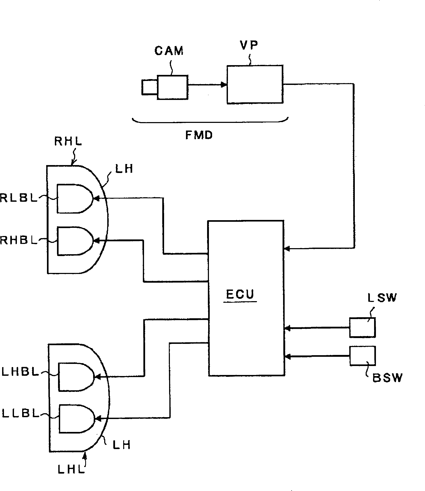
[0033] Next, Embodiment 1 of the present invention will be described. figure 1 It is a diagram showing the overall structure. The left and right headlamps LHL, RHL are connected to the lighting control device ECU, and the light switch LSW and the beam switch (dimmer switch ( ディマ一スイッチ)) BSW. The beam switch BSW switches the driving beam (high beam) and the passing beam (low beam) of the respective headlights LHL, RHL. In addition, a front vehicle detection device FMD for detecting other vehicles such as an oncoming vehicle or a preceding vehicle existing in the area in front of the vehicle is provided at the front part of the vehicle (not shown in the figure), and the above-mentioned switch is activated based on the detection output of the front vehicle detection device FMD. The lamp control unit ECU is capable of controlling turning on of the above-mentioned headlamps LHL, RHL.
[0034] The above-mentioned left and right headlamps LHL, RHL have a so-called 4-lamp structure in...
Embodiment 2
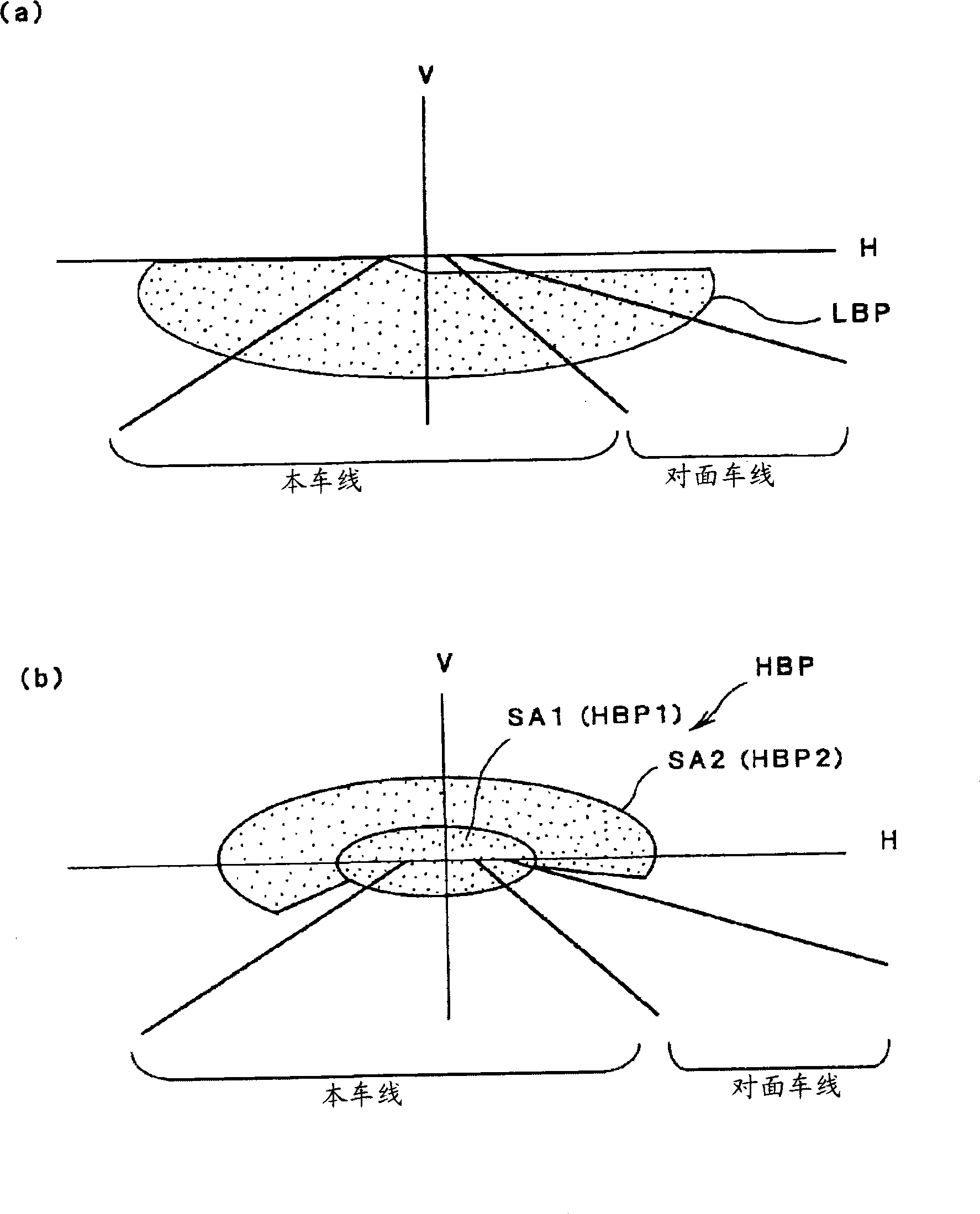
[0043] In Embodiment 1, the passing beam and the running beam are switched by the beam switch BSW operated by the driver, but in Embodiment 2, the passing beam and the running beam are switched based on the detection output of the preceding vehicle detection device FMD. switch. Such as Figure 6 As shown in the flow chart, if the light switch LSW is turned on (S21), the wrong vehicle beam lights RLBL, LLBH are turned on (S22). In this state, the front vehicle detection device FMD detects, for example, the preceding vehicle, and detects the inter-vehicle distance between the own vehicle and the preceding vehicle. When the inter-vehicle distance is smaller than the first prescribed distance, the light-on control device ECU only turns on the light for the wrong-way beam light, but does not turn on the light for the running light beam. That is, becomes as Figure 5 (a) Illumination of the light distribution pattern LBP of the passing beam shown in (a). When the inter-vehicle d...
Embodiment 3
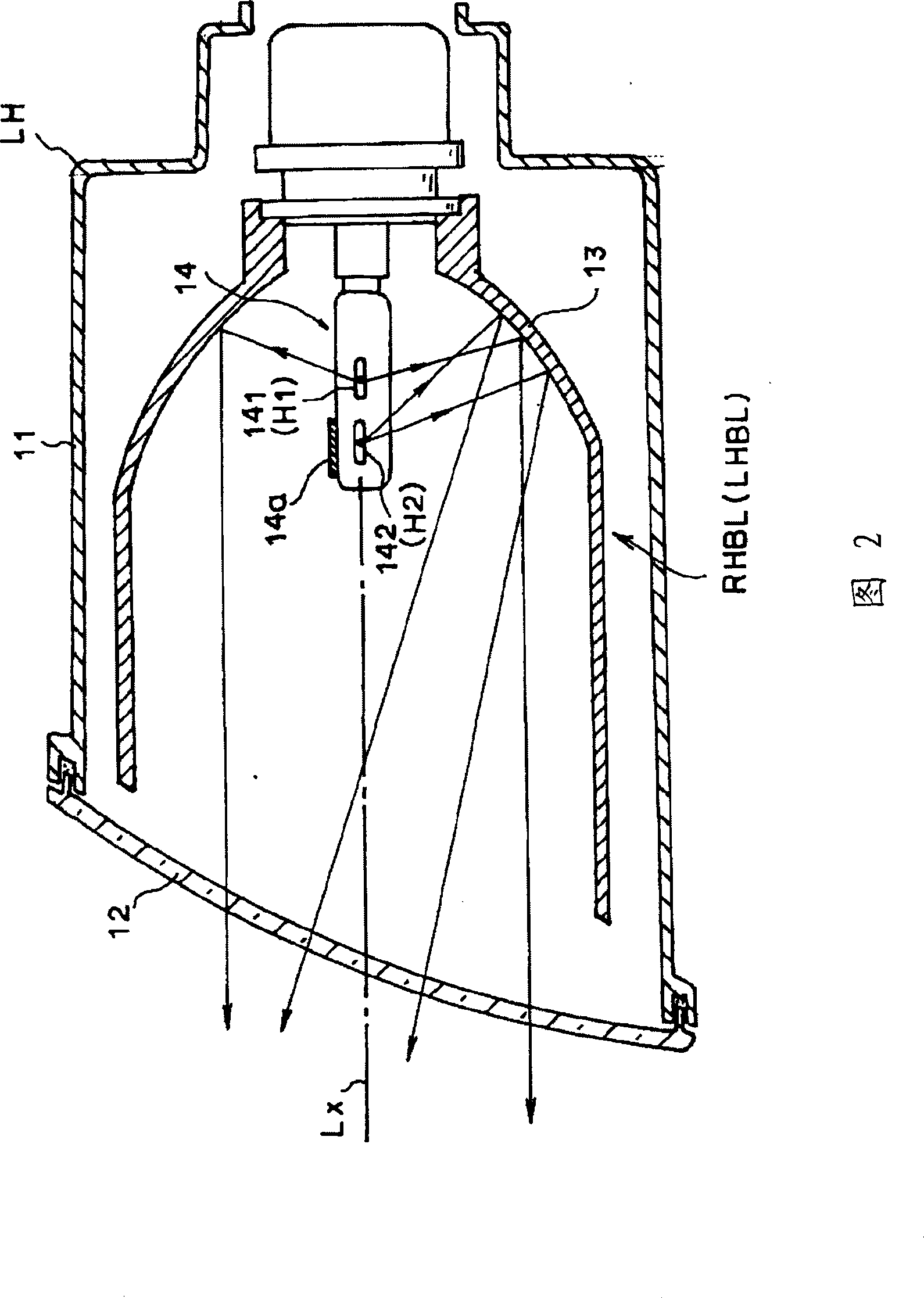
[0047] Fig. 7 is a schematic configuration diagram of a running beam lamp RHBL (LHBL) according to the third embodiment. This lamp is configured as a projection lamp, and its structure includes: a reflector 21 formed into a substantially spheroidal shape, a cylindrical bracket 22 installed on the front opening of the reflector 21, and a front surface of the bracket 22. Condenser lens 23 with opening. Inside the reflecting mirror 21, there is a single H light source 24 composed of a light bulb arranged at the first focal point of the reflecting mirror 21. As shown in FIG. The condensing lens 23 is configured as a convex lens, and its position is adjusted in the front-rear direction within a predetermined length range along the light axis Lx by the slide mechanism 25 provided on the bracket 22 as shown by the arrow in FIG. 7 . Above-mentioned slide mechanism 25 passes as figure 1 The illustrated turn-on control device ECU controls the position of the condenser lens 23 accordin...
PUM
 Abstract
Description
Claims
Application Information
 - R&D
- Intellectual Property
- Life Sciences
- Materials
- Tech Scout
- Unparalleled Data Quality
- Higher Quality Content
- 60% Fewer Hallucinations
Browse by: Latest US Patents, China's latest patents, Technical Efficacy Thesaurus, Application Domain, Technology Topic, Popular Technical Reports.
© 2025 PatSnap. All rights reserved.Legal|Privacy policy|Modern Slavery Act Transparency Statement|Sitemap|About US| Contact US: help@patsnap.com