Belt for lap forming device

A technology of winding device and cotton roll, which is applied in the belt field of winding device, can solve the problems of increasing fiber loss, machine pollution, frequent

Inactive Publication Date: 2009-05-06
MASCHINENFABRIK RIETER AG
View PDF3 Cites 3 Cited by
  • Summary
  • Abstract
  • Description
  • Claims
  • Application Information

AI Technical Summary

Problems solved by technology

[0007] This causes firstly a loss of quality during subsequent processing, secondly increases fiber loss and also leads to contamination of the machine
That is, maintenance intervals for cleaning machines have to be carried out at shorter intervals, i.e. more frequently

Method used


Image

  • Belt for lap forming device
  • Belt for lap forming device
  • Belt for lap forming device

Examples


Embodiment Construction

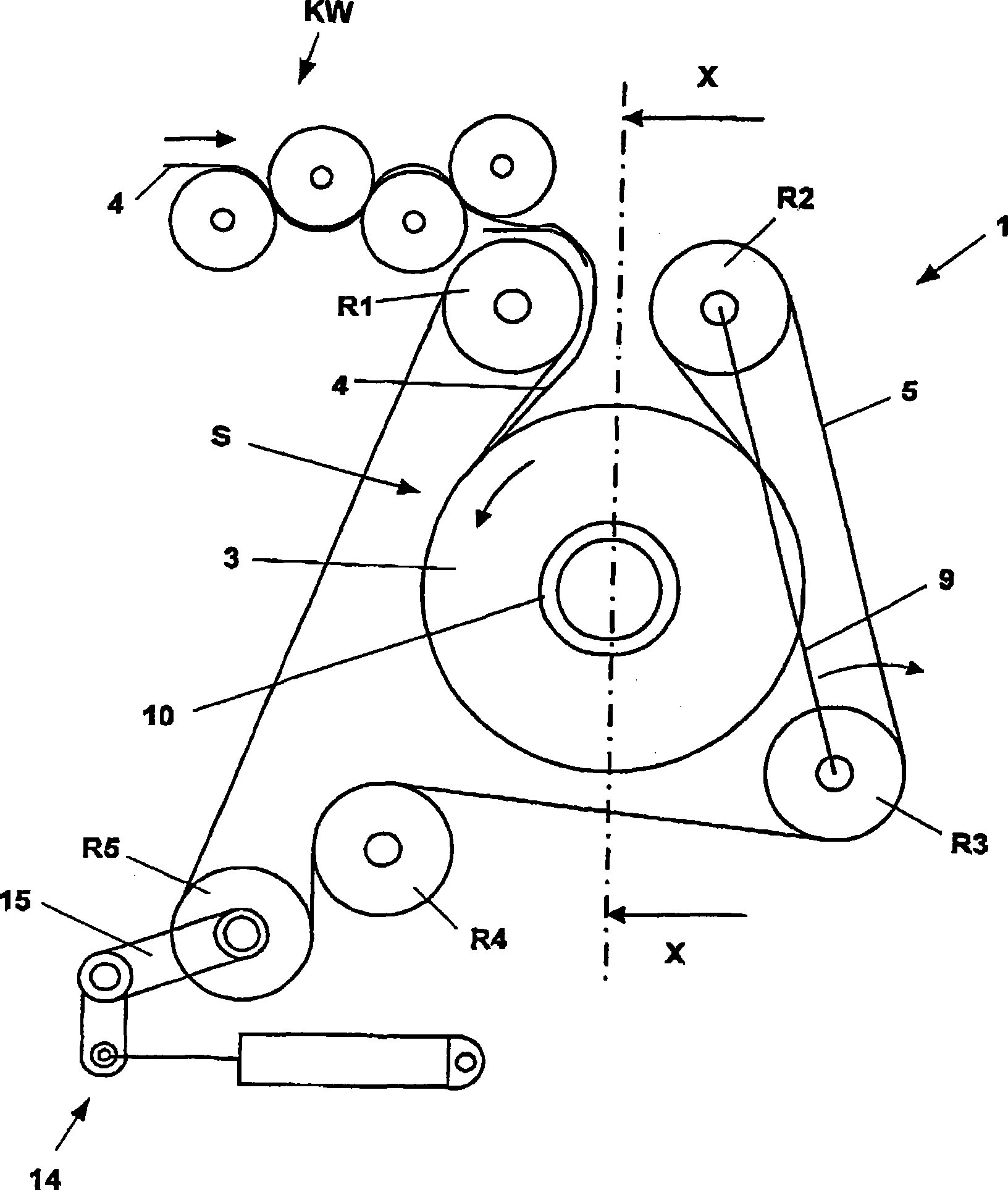
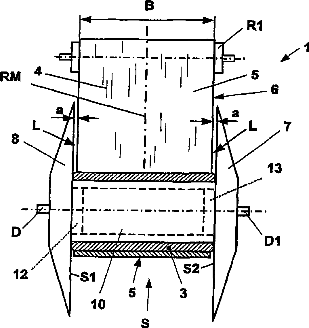
[0029] figure 1 Shown is a winding device 1 with a flat belt 5 guided on a plurality of deflection rollers R1 to R5. Between the deflection rollers R1 and R2, the belt 5 forms a loop S in which the lap 3 is formed. Here, in the winding operation, the lap sheet 4 (also called batt) fed into the loop by the calender rollers KW is wound on the sleeve 10 . Sleeve 10 passes through sockets 12 and 13 (see figure 2 ) is mounted in a fixed manner between the two winding discs 7, 8 so that the sleeve 10 can rotate along the axis of rotation D, D1.

[0030] As the lap 3 becomes larger, the size of the loop S also increases. In order to tension the belt 5 or to compensate for belt movement due to the enlargement of the loop S, a tensioning device 14 is provided. Here, the roller R5 is mounted by means of an arm 15 such that the roller R5 can rotate along the axis of rotation.

[0031] As soon as the lap 3 has reached its final size (determined and monitored by sensors), the batt 4 ...


PUM


Abstract

The present invention relates to a belt of coiling device (1) which is used for producing cotton roll (3), wherein the cotton roll (4) is coiled on a sleeve-shaped central spindle (10) which is driven by a circulating annular belt (5). The belt is provided with a plurality of layers (16, 17, 20) in a laminated mode when the belt is observed from the cross section. The belt comprises a first layer (16) which comprises a smooth surface (O) that is not adhered with fiber for producing a cleaning edge of cotton roll. The batting (4) is guided on the first layer (16) in the coiling process. The side edges (21, 21a, 22, 22a) of the other layers (17, 20) respectively retract from each side edge (19, 19a) of the first layer for a certain distance (b, b1, b2) when the belt is observed along the direction of central line (RM) of belt in the belt breadth (B).

Description

technical field [0001] The invention relates to a belt for a winding device for the production of laps, in which the batt is wound on a sleeve-shaped mandrel driven by an endless endless belt, said belt having a plurality of A layer above another. Background technique [0002] Document DE-195 39 365 A1 describes and discloses a winding device of this type for producing laps formed by using a flat belt. Here, a belt loop is placed around a sleeve, rotatably mounted on a fixed shaft, which adjusts its size as the winding diameter becomes larger and wraps the lap almost completely at the end of the winding operation. To form the lap, the lap sheet is inserted into the belt loop between two deflection rollers and conveyed to the surface of the sleeve. [0003] In order to guide the side edges of the lap sheet during the winding operation, there are side discs coaxial with the sleeve on each side, which support the side edges of the lap sheet during the winding process and faci...

Claims


Application Information

Patent Timeline
Patent Type & Authority Applications(China)
IPC IPC(8): D01G27/00B65H18/22
CPCB29D29/06D01G27/04D01G27/00
Inventor 布克哈德·怀曼费利克斯·凯勒
Owner MASCHINENFABRIK RIETER AG
Why Eureka
Try Eureka