

Tension self control structure for continuous crabbing machine
A kind of technology for fabricating machine and tension, which is applied in textile processing machine accessories, textiles and papermaking, and winding strips, etc. It can solve the problems of large range of fabric tension changes, low accuracy, and insufficient stability of fabric conveying, etc., to achieve control Accurate process and smooth fabric delivery
Inactive Publication Date: 2009-05-06
叶建清
View PDF0 Cites 2 Cited by
- Summary
- Abstract
- Description
- Claims
- Application Information
AI Technical Summary
Problems solved by technology
Due to the heavy weight of the iron mound and the large inertia of the iron mound, the swing range of the lever is likely to exceed the range required in the entire system, and the range of fabric tension changes is large, which may easily cause the fabric to be too tight or too loose in the entire conveying mechanism. The accuracy is low, and there are multiple tension self-control structures in the entire conveying mechanism, it is difficult to achieve synchronization between the structures, and the fabric conveying is not stable enough
Method used
View moreImage
Smart ImageViewing Examples

Examples
Embodiment Construction
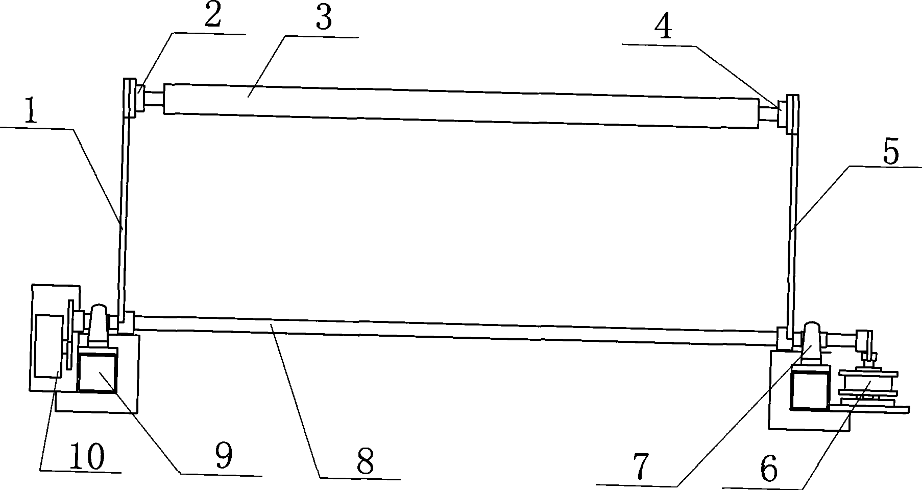
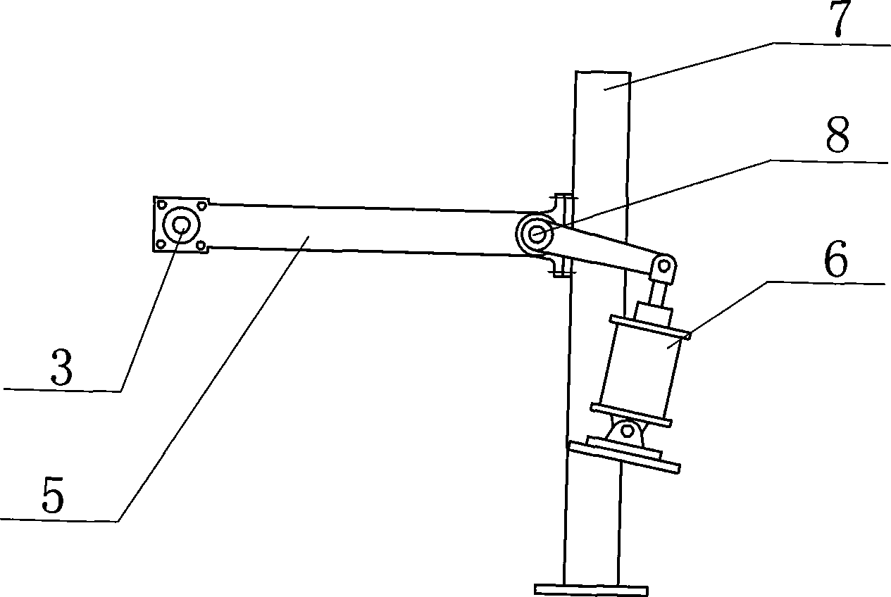
[0008] See figure 2 , the present invention comprises transmission shaft 8, and transmission shaft 8 is installed in bearing housing 7,9, and one end of transmission shaft 8 is connected with the piston rod of cylinder 6, and the other end of transmission shaft 8 is equipped with sensor 10, and sensor 10 and control cylinder 6 The electromagnetic valve is electrically controlled, and the two ends of the transmission shaft 8 are respectively sleeved and connected to the connecting rods 1 and 5, which are rotatably connected. The connecting rods 1 and 5 are connected to the guide roller 3 through the bearing seats 2 and 4 respectively.
Login to View More PUM
 Abstract
The invention relates to a tension autocontrol structure for a continuous crabbing machine. The tension autocontrol structure has high precision in controlling the rotation of a swinging rod; fabric has small amplitude of tension change in the whole transportation mechanism, can realize synchronization and has smooth transportation. The tension autocontrol structure is characterized in that the structure comprises a rotating shaft which is arranged on a bearing seat; one end of the rotating shaft is connected with a piston rod of a cylinder; the other end of the rotating shaft is provided with a sensor; the sensor is in electric control connection with an electromagnetic valve for controlling the cylinder; two ends of the rotating shaft are sleeved and connected with a connecting rod respectively; two ends of the rotating shaft and the connecting rods are in rotary connection; and the connecting rods are connected with a guide roller through the bearing seat respectively.
Description
(1) Technical field [0001] The invention relates to a component of a continuous decoiler, in particular to a tension self-control structure for a continuous decoiler. (2) Background technology [0002] The tension self-control structure of the existing continuous decal machine comprises an iron mound and a lever. A roller shaft is installed on one end of the lever, and the other end is connected to the iron mound. The fabric moves along the surface of the roller shaft. When the speed of the fabric is too fast during transmission, the tension of the fabric is greater, and the pressure on the roller shaft is greater. The lever rotates around its fulcrum to adjust the surface tension of the fabric. Due to the heavy weight of the iron mound and the large inertia of the iron mound, the swing range of the lever is likely to exceed the range required in the entire system, and the range of fabric tension changes is large, which may easily cause the fabric to be too tight or too loos...
Claims
Login to View More Application Information
Patent Timeline
 Patent Type & AuthorityApplications(China)
IPC IPC(8): D06B23/00B65H23/04
Inventor叶建清
Owner叶建清