Hollow carcass for filling cast-in-situ concrete

A hollow carcass, cast-in-situ concrete technology, which is applied to the on-site preparation of building components, formwork/template/work frame, structural elements, etc. question

Inactive Publication Date: 2009-05-06
湖南邱则有专利战略策划有限公司
View PDF6 Cites 1 Cited by
  • Summary
  • Abstract
  • Description
  • Claims
  • Application Information

AI Technical Summary

Problems solved by technology

But when this kind of hollow carcass is applied to the floor construction, the hollow carcass cannot be accurately arranged in the middle layer of the floor, which affects the construction quality of the floor
For this reason, the patent No. is ZL01215092.4, and the name is "building component" utility model patent. The disclosed building component is a polyhedron, which can be hollow or solid. In order to ensure that this building component is applied to the floor It is arranged in the middle layer of the floor, and the outer wall of the polyhedron is provided with protruding legs, so that when the floor is poured, the legs can ensure that the hollow multi-faceted main cavity is just at the middle layer of the floor. , so as to better solve the above problems, but this kind of building components is inconvenient to make during production, the production efficiency is low, it is not convenient for assembly line production, and the cost is high

Method used


Image

  • Hollow carcass for filling cast-in-situ concrete
  • Hollow carcass for filling cast-in-situ concrete
  • Hollow carcass for filling cast-in-situ concrete

Examples


Embodiment Construction

[0061] The present invention will be further described below in conjunction with the accompanying drawings and embodiments.

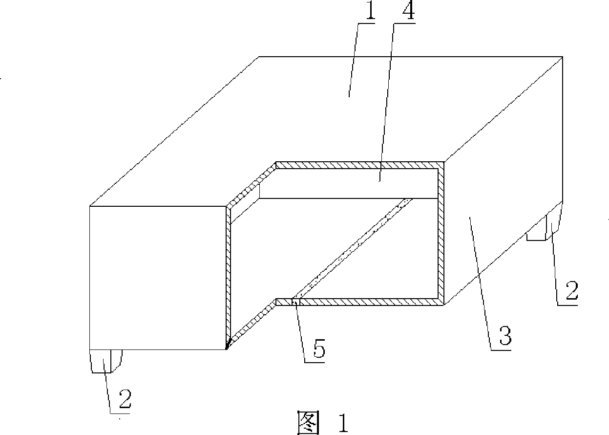
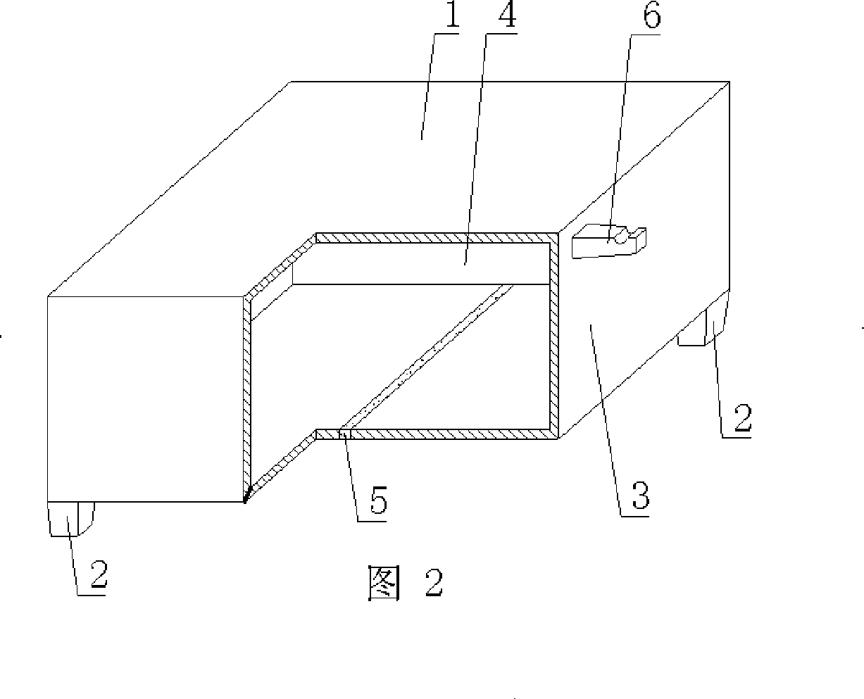
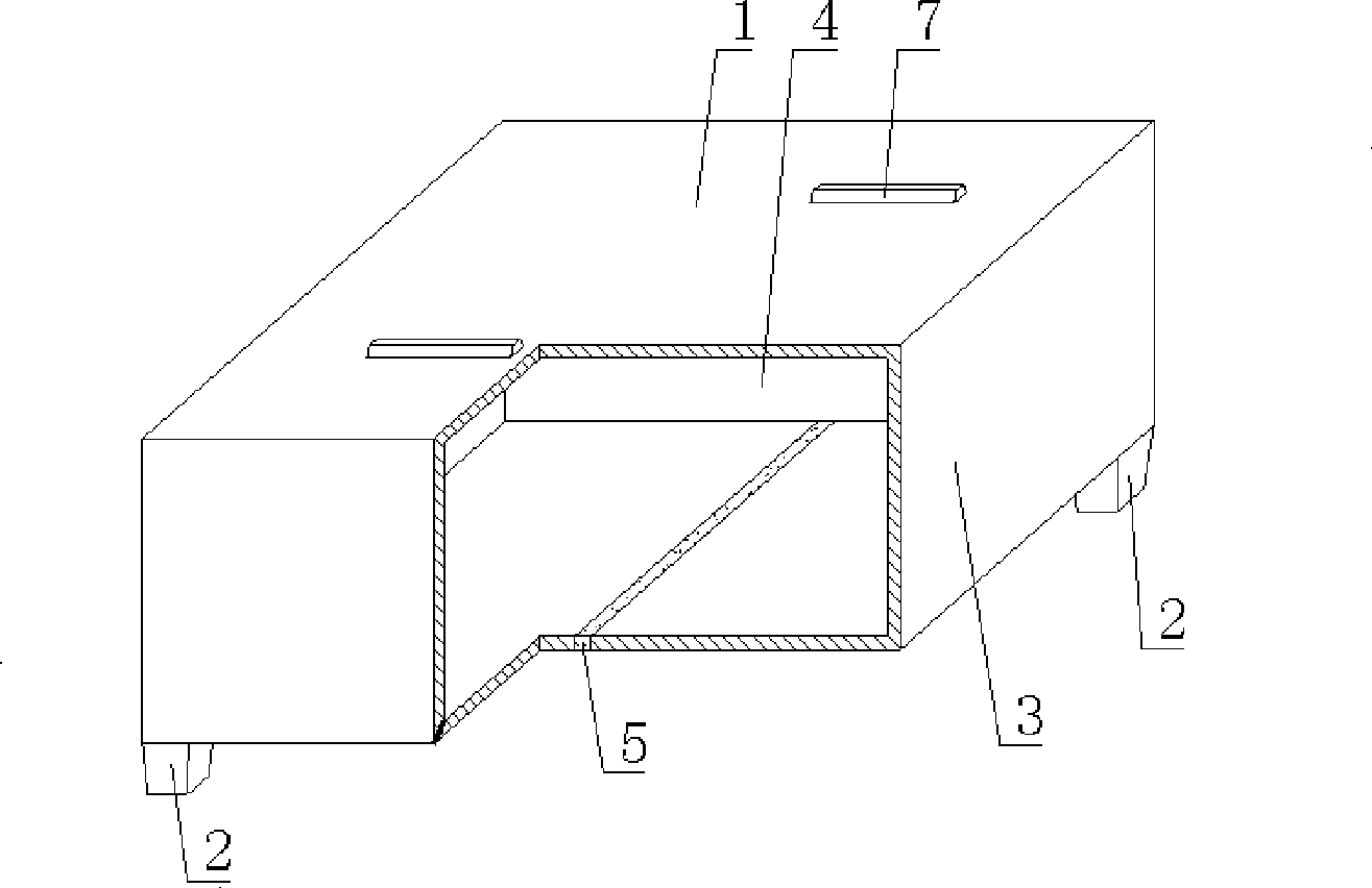
[0062] As shown in the accompanying drawings, the present invention includes a hollow carcass 1 and a support foot 2. The support foot 2 is arranged on the outer wall 3 of the hollow carcass 1, and the outer wall 3 encloses the hollow carcass 1 with a cavity 4, and is characterized in that On the outer wall 3 of the support foot 2, there is a cementing belt 5 joined by the embryo body edge of the outer wall 3 of the hollow carcass 1. The cementing belt 5 is arranged between the two support feet 2. The hollow carcass 1 is a polyhedron, and the support foot 2 or the outer wall At least one of 3 is provided with a reinforcement 9, and the reinforcement 9 is exposed outside the hollow carcass 1. In each accompanying drawing, 1 is a hollow carcass, 2 is a support foot, 3 is an outer wall, 4 is a cavity, and 5 is a cementing belt. In the following accompanyin...


PUM


Abstract

The invention relates to a hollow matrix for filling cast-in-situ concrete, which comprises a hollow matrix (1) and arm braces (2), wherein the arm braces (2) are arranged on the outer wall (3) of the hollow matrix (1), and the outer wall (3) are enclosed to form the hollow matrix (1) with a hollow cavity (4). The hollow matrix for filling the cast-in-situ concrete is characterized in that a cementation belt (5) which is joined with a matrix edge of the outer wall (3) of the hollow matrix (1) is arranged on the outer wall (3) of the hollow matrix(1) and arranged between two arm braces (2); the hollow matrix (1) is a polyhedron; and a reinforcement (9) is arranged inside at least one of arm braces (2) or the outer wall (3) and exposed out of the hollow matrix (1). The hollow matrix is suitable to be used for a hollow slab, a hollow floor, a hollow roof, a hollow wall body, a hollow base slab and a bridge which is filled with cast-in-situ reinforced concrete or prestressed reinforced concrete, and is particularly suitable to be used for a hollow girderless floor.

Description

[0001] This application is a divisional application of an invention patent application with an application date of September 2, 2004, an application number of 2004101552725, and a title of "a hollow matrix for filling cast-in-place concrete". (1) Technical field [0002] The invention relates to a hollow matrix for filling cast-in-place concrete. (2) Background technology [0003] At present, the cast-in-place concrete hollow floor is a widely used floor structure. The lightweight permanent tire molds filled in it include various hollow tubes and boxes, and the boxes are hollow or solid. For example, the patent No. ZL99249798.1, which the applicant applied for on November 29, 1999, is a utility model patent named "fiber-reinforced thin-walled member for reinforced concrete filling", which discloses a thin-walled formwork member, including an upper plate, The surrounding side walls, the lower bottom, and the upper plate, the surrounding side walls and the lower bottom form a ...

Claims


Application Information

Patent Timeline
IPC IPC(8): E04B5/36E04B5/48E04C5/00E04C5/16E04G11/36E04G15/06
Inventor 邱则有
Owner 湖南邱则有专利战略策划有限公司
Why Eureka
Try Eureka