Crank block type pumping unit
A crank-slider, pumping unit technology, applied in mechanical equipment, production fluids, wellbore/well components, etc., to achieve the effect of simple calculation, easy implementation, and long life
- Summary
- Abstract
- Description
- Claims
- Application Information
AI Technical Summary
Problems solved by technology
Method used
Image

Examples
Embodiment Construction
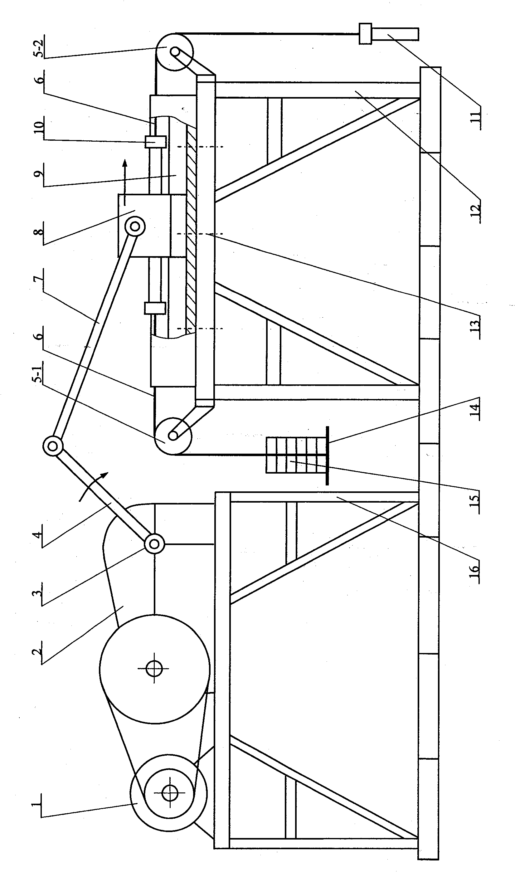
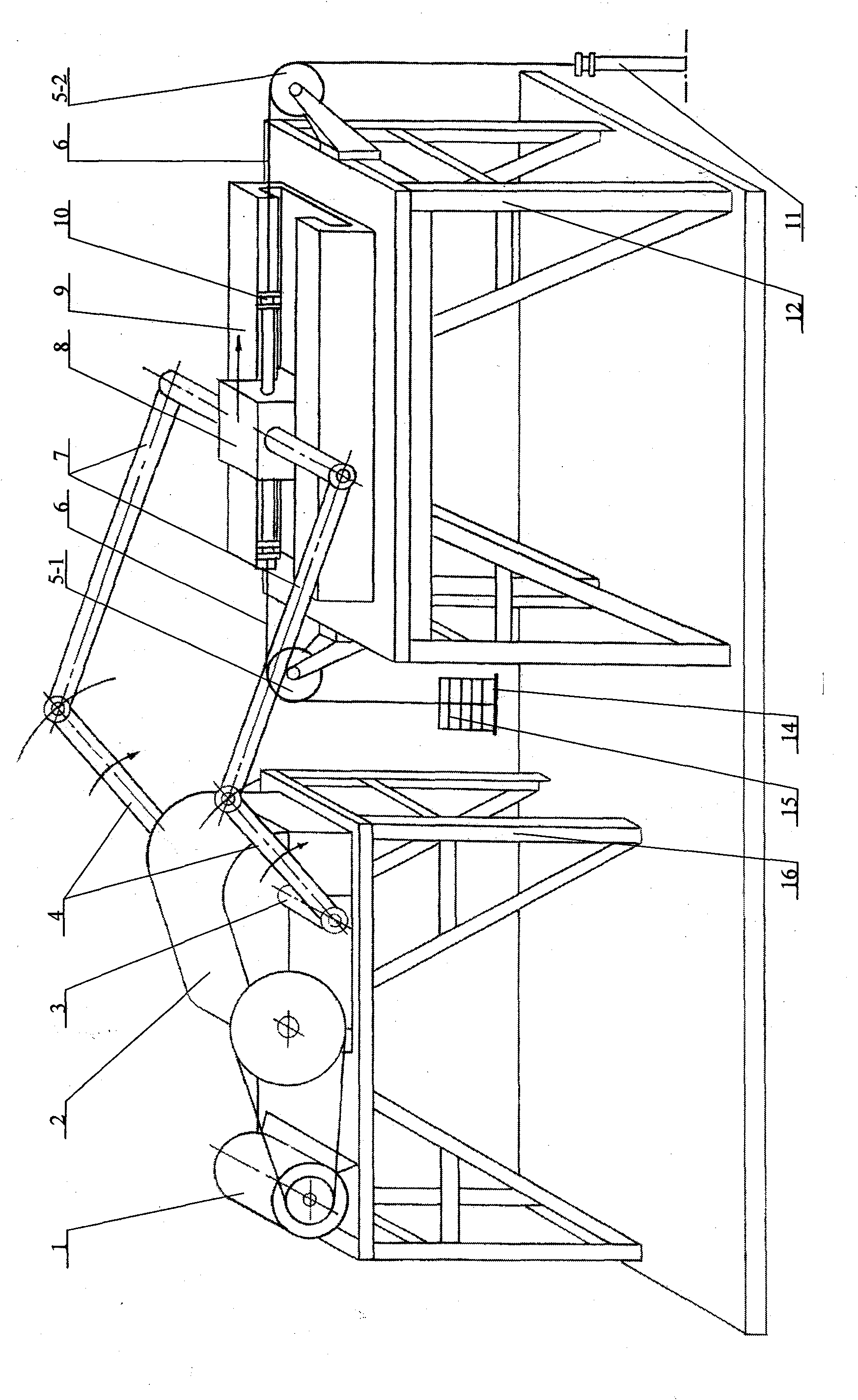
[0020] (1) Structural Implementation Description ( figure 1 , figure 2 )
[0021] The crank slider oil pumping unit includes an electric motor (1), a reducer (2), an output shaft of the reducer (3), a double crank (4), a first fixed pulley (5-1), a second fixed pulley (5- 2), steel rope (6), double connecting rod (7), slider (8), guide rail (9), rope rod connector (10), oil well pump plunger rod (11), crank slider mechanism bracket ( 12), bolts (13), counterweight tray (14), counterweight (15), reducer and motor bracket (16).
[0022] A double crank (4) is installed on the output shaft (3) of the reducer, and the double crank (4) is connected with a double connecting rod (7) through a pin shaft; the double connecting rod (7) is connected with a sliding block (8) through a pin shaft, and the sliding The extension shaft at the left end of the block (8) is connected with the balance weight pallet (14) through the rope rod connector (10), the left end steel rope (6) and the f...
PUM
 Abstract
Description
Claims
Application Information
 - R&D Engineer
- R&D Manager
- IP Professional
- Industry Leading Data Capabilities
- Powerful AI technology
- Patent DNA Extraction
Browse by: Latest US Patents, China's latest patents, Technical Efficacy Thesaurus, Application Domain, Technology Topic.
© 2024 PatSnap. All rights reserved.Legal|Privacy policy|Modern Slavery Act Transparency Statement|Sitemap