Oil lubricating structure

An oil and structure technology, applied in the direction of engine lubrication, pressure lubricant, lubricating parts, etc., can solve the problem of oil supply, inhalation into hydraulic devices such as oil pumps or valve bodies, and the front side of the bottom case. The oil return hole on the bottom surface of the main body case backflow to the first motor generator and power distribution device, etc.

Inactive Publication Date: 2009-05-06
TOYOTA JIDOSHA KK +1
View PDF1 Cites 37 Cited by
  • Summary
  • Abstract
  • Description
  • Claims
  • Application Information

AI Technical Summary

Problems solved by technology

[0005] However, with the above-mentioned oil lubricating structure, the oil return hole is formed on the bottom surface of the main body case on the front side of the oil pan, so when the vehicle brakes suddenly or travels downhill, in this case the oil The pan is tilted forward together with the main body case, and the oil stored in the oil pan may flow back to the first motor generator through the oil return hole formed on the bottom surface of the main body case on the front side of the oil pan. and power distribution
If this happens, the amount of oil in the oil pan may decrease sharply, so that air may be sucked into hydraulic devices such as the oil pump or valve body through the suction port, and a sufficient amount of oil may not be supplied to the first A motor generator and power distribution device

Method used


Image

  • Oil lubricating structure
  • Oil lubricating structure
  • Oil lubricating structure

Examples


Embodiment Construction

[0024] Exemplary embodiments of the present invention will be described in detail below with reference to the accompanying drawings.

[0025] Figure 1 to Figure 5D is a diagram of a first exemplary embodiment of the oil lubricating structure of the present invention, and shows an example of the application of the present invention to a driving device of a hybrid vehicle.

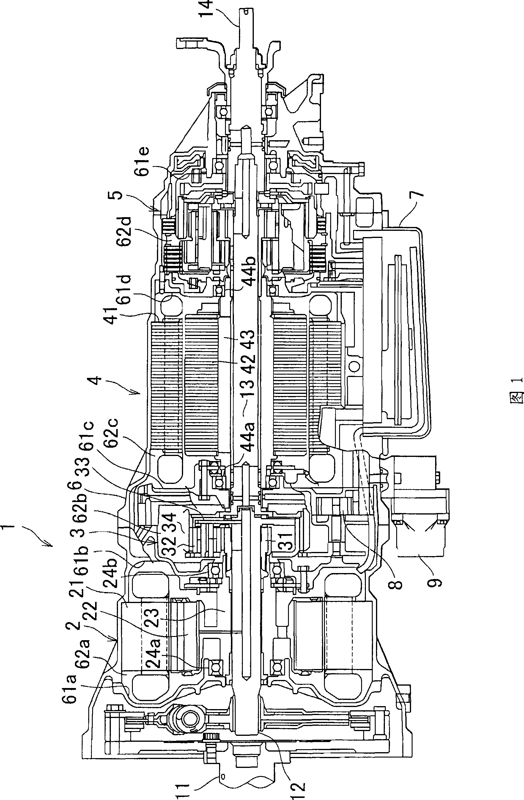
[0026] First, this structure will be described. As shown in FIG. 1 , a hybrid electric vehicle driving device 1 is a dual-motor hybrid electric vehicle driving device. The front end portion shown on the left side of the figure is connected to an engine not shown via the crankshaft 11 , and the rear end portion shown on the right side of the figure is connected to a transmission shaft also not shown. The hybrid vehicle driving device 1 has a first motor generator 2, a power distribution device 3, a second motor generator 4, and a speed change device 5, all of which are supplied inside a housing 6 serving a...


PUM


Abstract

An oil lubricating structure includes a main body case (6) having a housing chamber (62a) in which a first dynamotor (2) is housed; an oil sump (7) which is provided below the main body case (6) and has an oil chamber in which oil collects; an oil supply portion which has an inlet port (75a) through which oil is drawn in from the oil chamber and which supplies oil collected in the oil chamber to the first dynamotor (2) through the inlet port; and an oil return hole (63a) which is formed in a bottom surface of the main body case (6) toward the front of the oil sump (7). A duct member (73) is provided in the oil chamber. One end portion (73a) of the duct member (73) is connected to the oil return hole (63a) and the other end portion (73b) of the duct member (73) is positioned farther to the rear than the inlet port (75a). Thus, an oil lubricating structure, which can prevent air from being sucked into the inlet port (75a) with the condition that the oil sump (7) and the main body case (6) are forward tipping when the vehicle is braked or move downwards, is provided.

Description

technical field [0001] The invention relates to an engine oil lubricating structure, especially an engine oil lubricating structure suitable for supplying engine oil sucked from an oil storage tank to an oil-supplied element, and then returning the engine oil to the oil storage tank. Background technique [0002] Generally, in an oil lubricating configuration of a vehicle such as an automobile, an oil pan serving as an oil storage tank is mounted on a lower portion of a main body case of a transmission. The oil stored in the oil pan is sucked by an oil pump through a suction port formed on the strainer and supplied to an oil-supplied element such as a transmission gear constituting part of a transmission. The engine oil cools or lubricates the oil-supplied element while flowing downward along the main body case, and finally returns to the oil pan through the oil return hole formed in the lower part of the main body case. [0003] Japanese Patent Application Publication No. ...

Claims


Application Information

Patent Timeline
Patent Type & Authority Applications(China)
IPC IPC(8): F16H57/04F16H57/02B60K6/20B60K17/04F01M11/03B01D35/02F16N7/38F16N31/00
CPCF16H57/0484Y02T10/6239F16H57/0476B60K1/02F16H57/0424F16H57/0445F16H57/0443B60K6/547F16H57/0404B60K6/365B60K6/445B60K6/405Y02T10/62
Inventor 佐藤彰洋本池一利松下淳二
Owner TOYOTA JIDOSHA KK
Why Eureka
Try Eureka