Warm wind blower

A blower, warm air technology, applied in air heaters, lighting and heating equipment, climate change adaptation, etc., can solve the problems of worsening fuel consumption, low heat exchange efficiency, low heat exchange rate, etc., to improve fuel consumption, increase Contact area, the effect of improving the heat exchange rate

Inactive Publication Date: 2009-05-06
ETO SHIPCCONSTR
View PDF1 Cites 1 Cited by
  • Summary
  • Abstract
  • Description
  • Claims
  • Application Information

AI Technical Summary

Problems solved by technology

[0005] However, in the above-mentioned conventional warm air blower, the heat exchange efficiency between the air passing through the casing and the heat source is low, which deteriorates fuel consumption.
That is, since the air sucked into the casing passes near the heat source at a predetermined flow rate, it is difficult to ensure a sufficient contact time with the heat source until it is exhausted from the exhaust port, resulting in a low heat exchange rate and high fuel consumption. waste of land

Method used


Image

  • Warm wind blower
  • Warm wind blower
  • Warm wind blower

Examples


Embodiment Construction

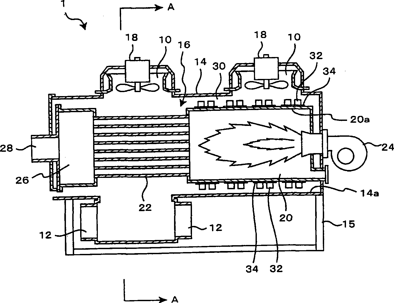
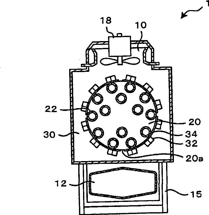
[0025] Hereinafter, embodiments of the present invention will be specifically described with reference to the drawings. figure 1 It is a side sectional view of the warm air blower according to the embodiment of the present invention, figure 2 yes figure 1 A-A sectional view of the warm air blower shown. In addition, the warm air blower according to the present embodiment may be installed in any place as long as heating is required, such as in a house for gardening or in a factory.

[0026] Such as figure 1 and figure 2 As shown, the warm air blower 1 according to the present embodiment includes a housing 14 having an air inlet 10 and an exhaust port 12, a heat source 16 provided in the housing 14, and a heat source 16 for sucking air from the air inlet 10 into the housing. The blower fan 18 of the blower mechanism that makes the air in the housing 14 exhaust from the exhaust port 12 in the body 14 . The heat source 16 is composed of a combustion chamber 20 and a smoke p...


PUM


Abstract

The invention provides a warm air blower capable of improving heat exchange rate between air and a heat source in a housing and ameliorating combustion of fuel. The invention is provided with: the housing (14) having a suction opening (10) and an exhaust opening (12); the heat source (16) provided within the housing (14); and an air feeding mechanism (18) for sucking the air from the suction opening (10) into the housing (14), exhausting the air within the housing (14) from the exhaust opening (12), and heating the air sucked into the housing (14) via the heat source (16) to exhaust from the exhaust opening (12) in a form of warm air; the heat source (16) includes a combustion chamber (20) that heats and radiates an internal combustor (24), a plurality of radiating fins (32) are provided over outer circumference of wall bodies (20a) constituting the combustion chamber (20).

Description

technical field [0001] The present invention relates to a warm air blower used for heating a house for facility gardening or a factory. Background technique [0002] In the past, as a warm air blower used for heating a house for gardening or a factory, as described in Patent Document 1, it is known to have a housing having an air inlet and an exhaust port, a heat source provided in the housing, And the warm air blower of the air supply mechanism that sucks air into the casing from the suction port and exhausts the air in the casing from the exhaust port. [0003] In this conventional warm air blower, air sucked into the housing is heated by a heat source and discharged as warm air from an exhaust port. [0004] [Patent Document 1] Japanese Patent Application Laid-Open No. 5-133610 [0005] However, in the above-mentioned conventional warm air blower, the heat exchange efficiency between the air passing through the casing and the heat source is low, which deteriorates fuel ...

Claims


Application Information

Patent Timeline
IPC IPC(8): F24H3/10F24H9/18
CPCY02A40/25
Inventor 江藤诚
Owner ETO SHIPCCONSTR
Why Eureka
Try Eureka