Radiator structure

A heat sink and heat dissipation fin technology, which is applied in the fields of instruments, cooling/ventilation/heating transformation, electrical digital data processing, etc., can solve the problems of unable to dissipate heat from fans, poor heat dissipation performance, etc., and achieve the effect of increasing thermal cycle efficiency

Inactive Publication Date: 2009-05-06
INVENTEC CORP
View PDF0 Cites 11 Cited by
  • Summary
  • Abstract
  • Description
  • Claims
  • Application Information

AI Technical Summary

Problems solved by technology

[0008] The object of the present invention is to provide a heat sink structure to improve the known heat dissipation devices used in portable electronic devices, which must cooperate with the internal circuit wiring of the electronic device, and cannot use fans to dissipate heat, only through the surface of the heat sink and the air contact, and dissipate heat by natural convection, resulting in poor overall cooling performance

Method used


Image

  • Radiator structure
  • Radiator structure
  • Radiator structure

Examples


Embodiment Construction

[0035] In order to have a further understanding of the purpose, structure, features, and functions of the present invention, the following detailed descriptions are provided in conjunction with the embodiments.

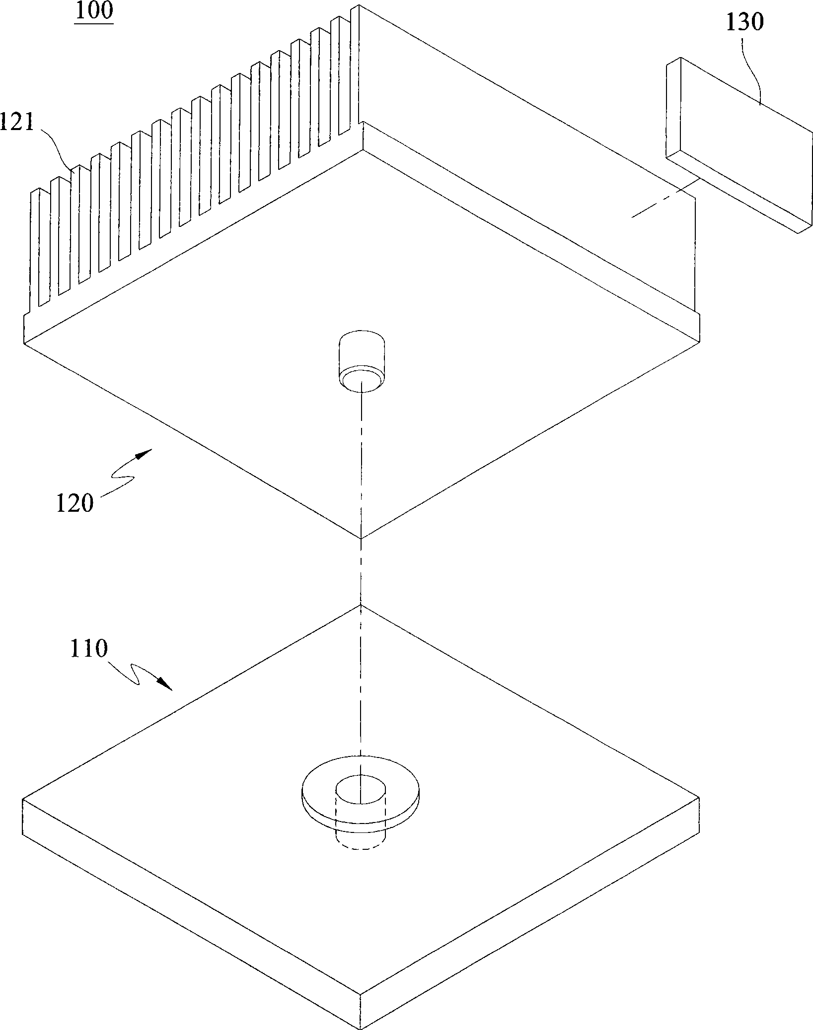
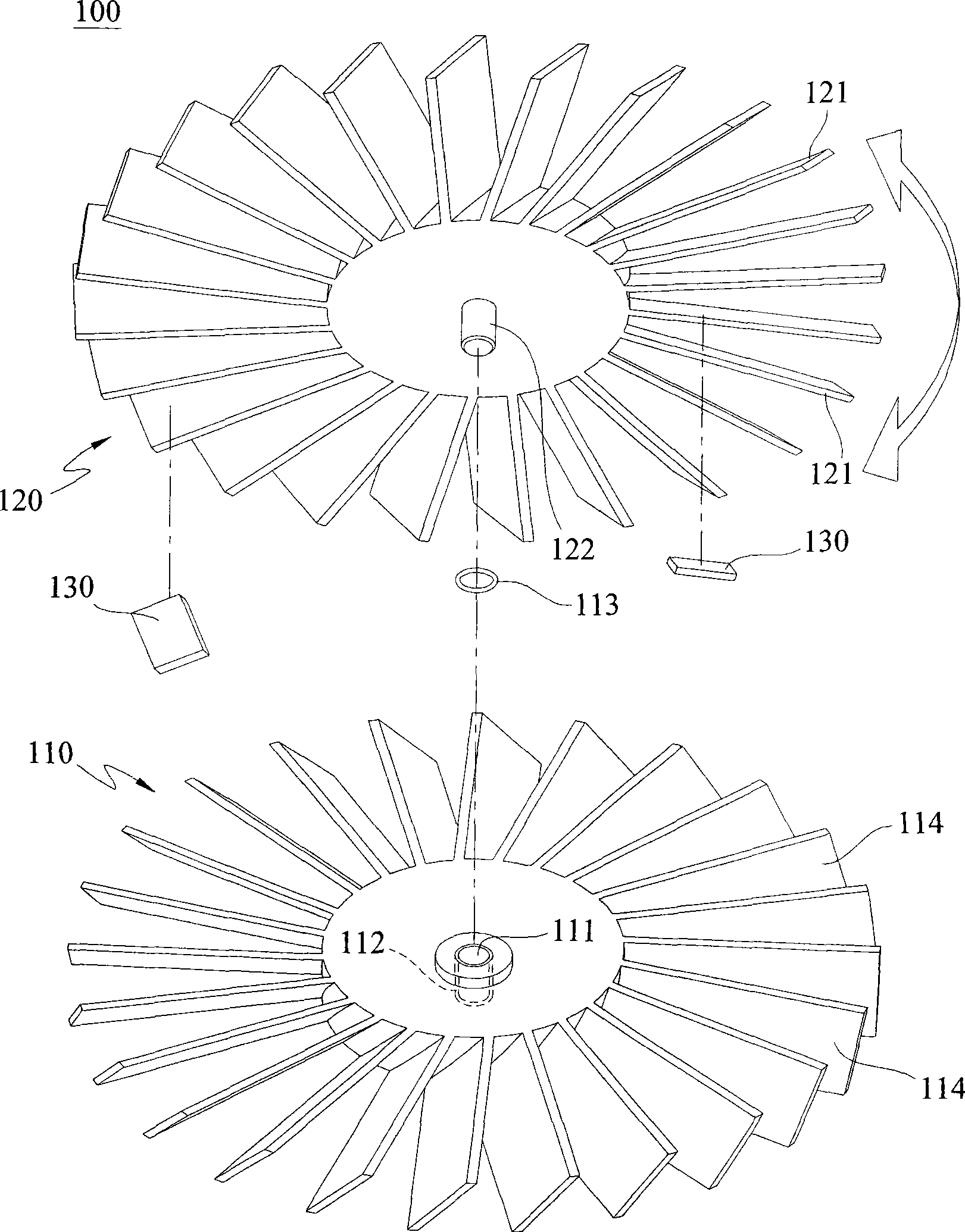
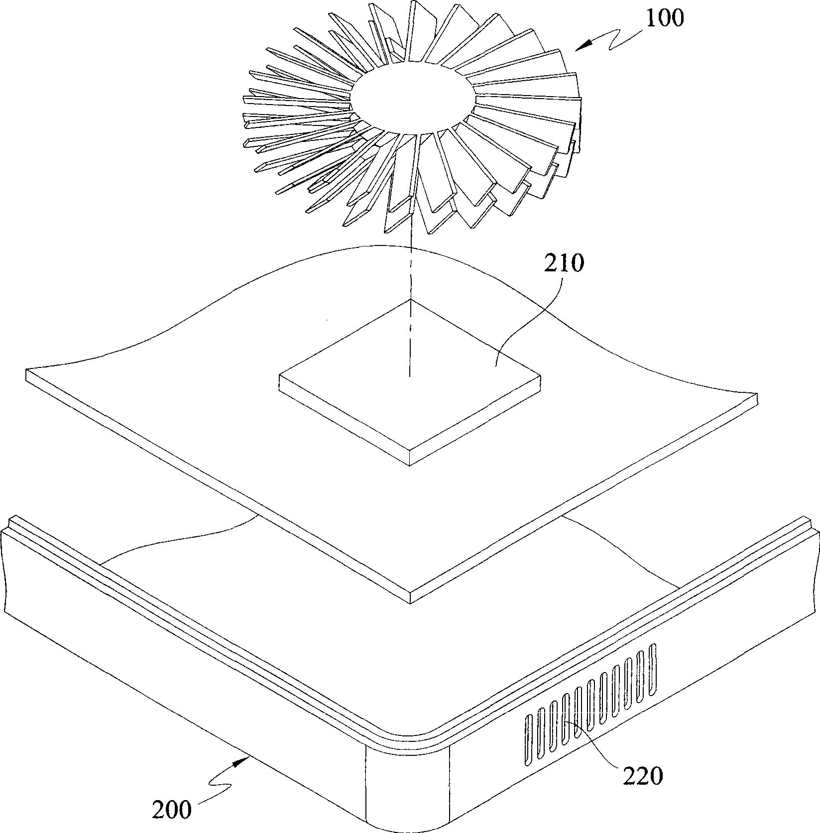
[0036] The radiator structure disclosed in the present invention is used to dissipate heat generated by electronic devices, including but not limited to portable electronic devices such as ultra-mobile computers (UMPCs), personal computers, notebook computers, and PDAs. In the following detailed description of the present invention, an ultra-portable computer will be taken as the preferred embodiment of the present invention. However, the accompanying drawings are provided for reference and illustration only, and are not intended to limit the present invention.

[0037] figure 1 Shown is an exploded schematic view of the radiator of the present invention. The heat sink 100 of the present invention includes a contact seat 110 , a fin seat 120 and a counterweight 130 ...


PUM


Abstract

The invention relates to a radiator structure which is arranged in an electronic device and is used for exchanging heat with an electronic component of the electronic device. The radiator structure comprises a contact socket and a fin socket, wherein the contact socket is clung on the electronic component for the heat transmission. The fin socket is pivoted on the contact socket so as to transmit heat with the contact socket, the fin socket is provided with a plurality of radiating fins and can rotate opposite to the contact socket through using a rotating shaft as the axes, and the gravity center of the fin socket is offset outside the rotating shaft. When electronic device is moved, the fin socket rotates because of the offset gravity center and causes the radiating fins to disturb air at the inner part of the electronic device.

Description

technical field [0001] The invention relates to a radiator structure, in particular to a radiator structure applied to portable electronic devices. Background technique [0002] With the rapid development of electronic technology and consumers' increasing emphasis on the lightness and portability of consumer electronic products, today's electronic products, such as notebook computers, ultra mobile personal computers (UMPC), PDA and other portable Electronic devices have been gradually miniaturized. For users who need to go out frequently, portable electronic products have become easier to carry, greatly improving the convenience of use. [0003] Due to the fast calculation speed of the electronic devices inside the computer device, coupled with the small size of the electronic devices, the calorific value per unit area will increase accordingly. If the heat energy is not dissipated in time, the high temperature will seriously affect the electronic devices. Stability and eff...

Claims


Application Information

Patent Timeline
Patent Type & Authority Applications(China)
IPC IPC(8): G06F1/20H05K7/20
Inventor 王锋谷王少甫黄庭强许圣杰
Owner INVENTEC CORP
Why Eureka
Try Eureka