High-frequency clock detection circuit
A high-speed clock and detection circuit technology, applied in frequency measurement devices, electrical digital data processing, instruments, etc., can solve problems such as clock signal period limitation
- Summary
- Abstract
- Description
- Claims
- Application Information
AI Technical Summary
Problems solved by technology
Method used
Image

Examples
no. 1 Embodiment
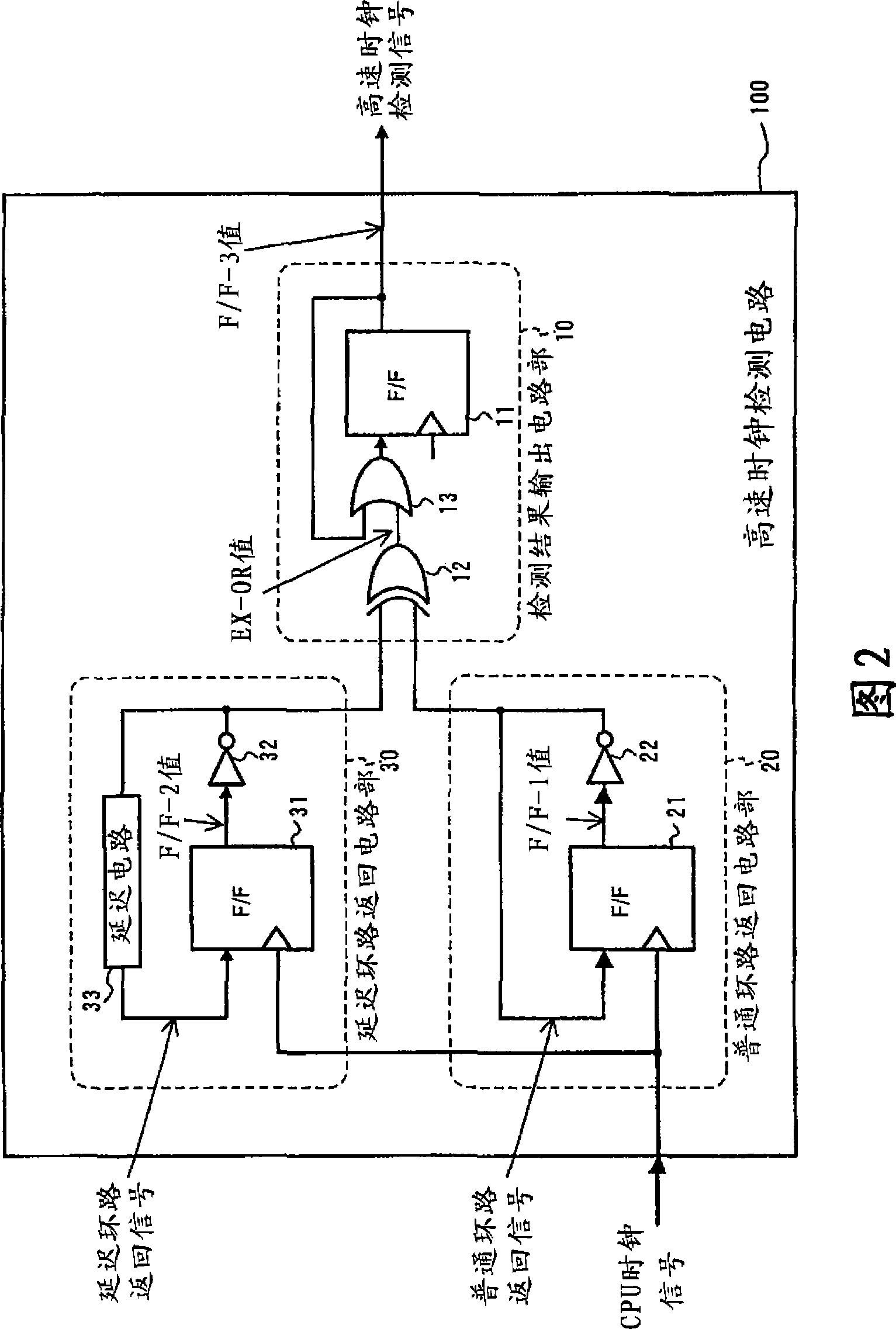
[0022] FIG. 2 shows a first embodiment of the present invention, showing the configuration of a high-speed clock detection circuit. The high-speed clock detection circuit 100 is roughly divided into three circuit sections, and is composed of a normal loop return circuit section 20 , a delay loop return circuit section 30 , and a detection result output circuit section 10 .
[0023] The common loop return circuit part 20 includes a D (delay) type flip-flop circuit 21 and an inversion circuit 22, the output signal (F / F-1 value) of the flip-flop circuit 21 is inverted by the inversion circuit 22, and the obtained inverse The transfer signal is simply looped back and fed back to the trigger circuit 21 as a common looped back signal. In addition, a CPU clock signal input from the outside is supplied to the clock terminal of the flip-flop circuit 21 .
[0024] The delay loop return circuit section 30 includes a D (delay) type flip-flop circuit 31 and an inversion circuit 32 and a d...
Embodiment 2
[0039] Fig. 5 shows a second embodiment of the present invention, showing the configuration of a high-speed clock detection circuit. The high-speed clock detection circuit 100 is composed of a normal loop return circuit section 20 , a delay loop return circuit section 30 , and a detection result output circuit section 10 . The normal loop return circuit unit 20 and the delay loop return circuit unit 30 in the second embodiment have the same configuration as those in the first embodiment.
[0040] In the second embodiment, the configuration of the detection result output circuit unit 10 is different from that of the first embodiment. The detection result output circuit unit 10 includes an exclusive OR circuit 12 and a counter 14 which can be realized by a plurality of flip-flop circuits. The exclusive OR circuit 12 inputs an exclusive OR value (EX-OR value) of the inverted signal from the normal loop return circuit section 20 and the inverted signal from the delay loop return ...
Embodiment 3
[0046] Fig. 7 shows a third embodiment of the present invention, showing the configuration of a high-speed clock detection circuit. The high-speed clock detection circuit 100 is composed of a normal loop return circuit unit 20 , a delay loop return circuit unit 30 and a detection result output circuit unit 10 , and also includes a count threshold setting register 41 and a bus interface 42 . The normal loop return circuit unit 20 and the delay loop return circuit unit 30 in the third embodiment have the same configuration as those in the first and second embodiments.
[0047] The detection result output circuit unit 10 in the third embodiment has the function of changing the count threshold by referring to the count threshold setting register 41 in addition to the configuration in the second embodiment. The content of the count threshold setting register 41 is set by executing software in the control circuit (see FIG. 2 ) via the bus interface 42 . The counter 14 outputs a hig...
PUM
 Abstract
Description
Claims
Application Information
 - R&D
- Intellectual Property
- Life Sciences
- Materials
- Tech Scout
- Unparalleled Data Quality
- Higher Quality Content
- 60% Fewer Hallucinations
Browse by: Latest US Patents, China's latest patents, Technical Efficacy Thesaurus, Application Domain, Technology Topic, Popular Technical Reports.
© 2025 PatSnap. All rights reserved.Legal|Privacy policy|Modern Slavery Act Transparency Statement|Sitemap|About US| Contact US: help@patsnap.com