Electromagnetic permanent magnet combined driving apparatus

A driving device and permanent magnet technology, applied in electromechanical devices, power devices inside switches, circuits, etc., can solve problems such as inability to move as a whole, poor transient performance of actions, and hidden dangers of fatigue failure, so as to achieve simple overall mechanism and fast opening and closing action , The effect of high driving efficiency

Inactive Publication Date: 2009-05-06
SHANGHAI JIAO TONG UNIV
View PDF1 Cites 27 Cited by
  • Summary
  • Abstract
  • Description
  • Claims
  • Application Information

AI Technical Summary

Problems solved by technology

Although the device is also driven by a composite magnetic field of electromagnetic and permanent magnets, the driving efficiency is high and the driving process is easy to realize, but the output displacement of the driving device is always determined by the joint action of electromagnetic force, permanent magnetic force and external spring force, so , the accuracy of the driving displacement is affected by the accuracy of the real-time excitation current, and it is easy to generate displacement fluctuations. In the case of power failure, the driving displacement position cannot be maintained.
Moreover, since the spring is a fatigue-prone part, if it is used for a long time, such as driving for more than one million times, there may be hidden dangers of fatigue failure, which will affect the safety and stability of the long-term operation of the device
In addition, the central permanent magnet of the permanent magnet telescopic mechanism can only rotate but cannot move as a whole, so its driving displacement is gradually formed with the rotation of the central permanent magnet, and the action is not instantaneous, and the driving stroke also depends on the central permanent magnet itself size, these are not conducive to forming an instantaneous large stroke impact drive

Method used


Image

  • Electromagnetic permanent magnet combined driving apparatus
  • Electromagnetic permanent magnet combined driving apparatus
  • Electromagnetic permanent magnet combined driving apparatus

Examples


Embodiment 1

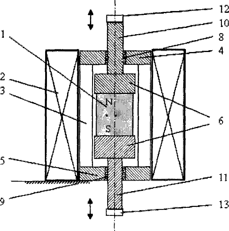
[0033] Such as figure 1 As shown, this embodiment includes: a permanent magnet moving body, an electromagnetic coil 2, a sleeve, an upper magnetically permeable cover 4, a lower magnetically permeable cover 5, an upper force output rod 10, and a lower force output rod 11, wherein the sleeve is a non- The magnetically conductive rigid frame 3, the permanent magnet mobile body is composed of a permanent magnet 1 sandwiched between two ferromagnetic bodies 6, the permanent magnet 1 and the ferromagnetic body 6 are fixedly connected, and the permanent magnetic mobile body is placed on a rigid upper guide In the space formed by the fixed connection of the magnetic cover 4, the lower magnetically conductive cover 5 and the non-magnetically conductive rigid frame 3, the two ends of the permanent magnet moving body are respectively fixedly connected with the upper force output rod 10 and the lower force output rod 11, and the upper force output The rod 10 and the lower force output ro...

Embodiment 2

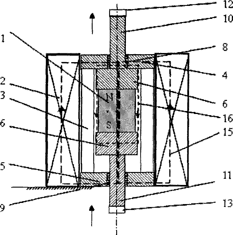
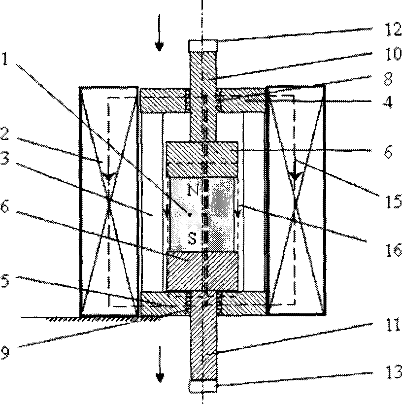
[0041] Such as Figure 4 As shown, this embodiment includes: a permanent magnet moving body, an electromagnetic coil 2, a sleeve, an upper magnetically permeable cover 4, a lower magnetically permeable cover 5, an upper bearing 8, an upper bearing 9, an upper force output rod 10, and a lower force output rod 11. The upper block 12 and the lower block 13, wherein: the sleeve is a non-magnetic rigid frame 3, the permanent magnetic moving body is composed of a ferromagnet 6 and a permanent magnet 1, and the ferromagnet 6 is used as the central body, and the outer side is covered with a tubular permanent magnet. The magnet 1, the permanent magnet 1 and the ferromagnet 6 are fixedly connected, the outer end faces of the permanent magnet moving body are fixedly connected with the upper force output rod 10 and the lower force output rod 11 respectively, and the permanent magnet moving body is placed on a rigid upper guide In the space formed by the fixed connection of the magnetic co...

Embodiment 3

[0049] Such as Figure 7 As shown, this embodiment includes: a permanent magnet moving body, an electromagnetic coil 2, a sleeve, an upper magnetically permeable cover 4, a lower magnetically permeable cover 5, an upper bearing 8, a lower bearing 9, an upper force output rod 10, and a lower force output rod 11, wherein: the sleeve is a ferromagnetic rigid outer shell 17, the permanent magnetic moving body is composed of a ferromagnet 6 and a permanent magnet 1, the ferromagnet 6 is used as a central body, and the outer side is covered with a tubular permanent magnet 1, permanent magnet 1 and ferromagnet 6 The outer end faces of the permanent magnet mobile body are fixedly connected with the upper force output rod 10 and the lower force output rod 11 respectively, and the permanent magnet mobile body is placed on a rigid upper magnetic cover 4, a lower magnetic cover 5 and In the space formed by the fixed connection of the rigid non-magnetic sleeve 3, the upper force output rod...


PUM


Abstract

The invention relates to an electromagnetic permanent composite driving switch and an impact mechanism, comprising a permanent-magnet moving body, an electromagnetic coil, a sleeve, an upper magnetic conductive cover, a lower magnetic conductive cover, an upper force output bar and a lower force output bar, wherein the permanent-magnet moving body is arranged in a space formed by the upper magnetic conductive cover, the lower magnetic conductive cover and the sleeve which are fixedly connected, the permanent-magnet moving body is also arranged inside the electromagnetic coil, the spacing between the upper magnetic conductive cover and the lower magnetic conductive cover is more than the length of the permanent-magnet moving body, the upper and the lower ends of the permanent-magnet moving body are respectively and fixedly connected with the upper force output bar and the lower force output bar, the upper force output bar and the lower force output bar respectively penetrate through through holes in the middle of the upper magnetic conductive cover and the lower magnetic conductive cover, the permanent-magnet moving body is a single permanent magnet and a permanent ferromagnetic composite body, and the permanent ferromagnetic composite body is formed by a permanent magnet and a ferromagnet which are fixedly connected. The invention has the advantages that the overall structure is simple, the instantaneous suction without partial vibration can be formed, the opening and the closing are stable, the opening and closing actions are quick and accurate without fluctuation, and the power failure stability retention at the opening or the closing position can be realized.

Description

technical field [0001] The invention relates to a device in the technical field of electromagnetic drive, in particular to an electromagnetic permanent magnet composite drive device. Background technique [0002] At present, in the application practice of drive technology, it is found that there is a great need for some drive devices that are relatively small in size, but can generate large drive force, and have stable power-off position maintenance. The application of this kind of device, such as in the field of electric power technology, the precise synchronous switching operation of vacuum circuit breakers, realizes the synchronous action of "voltage zero-crossing conduction and current zero-crossing cut-off", which is helpful to avoid high-voltage discharge arcs and inrush currents, and avoid burning contacts. The service life of the vacuum contactor is of great significance. [0003] After searching the existing technical literature, it is found that the Chinese patent...

Claims


Application Information

Patent Timeline
Patent Type & Authority Applications(China)
IPC IPC(8): H02K33/18H01H33/666H01H3/28
Inventor 杨斌堂孟光
Owner SHANGHAI JIAO TONG UNIV
Why Eureka
Try Eureka