Formwork component
A formwork member and component technology, applied in the field of formwork members, can solve the problems of poor overall strength and rigidity of formwork members, force and force transmission of cast-in-place concrete hollow floors, damage to formwork members, etc.
- Summary
- Abstract
- Description
- Claims
- Application Information
AI Technical Summary
Problems solved by technology
Method used
Image

Examples
Embodiment Construction
[0052] The present invention will be further described below in conjunction with the accompanying drawings and embodiments.
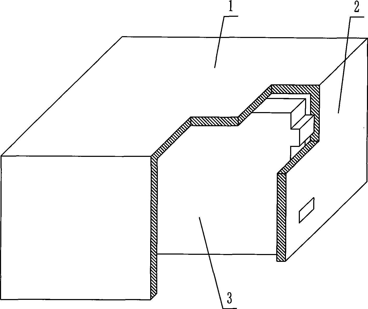
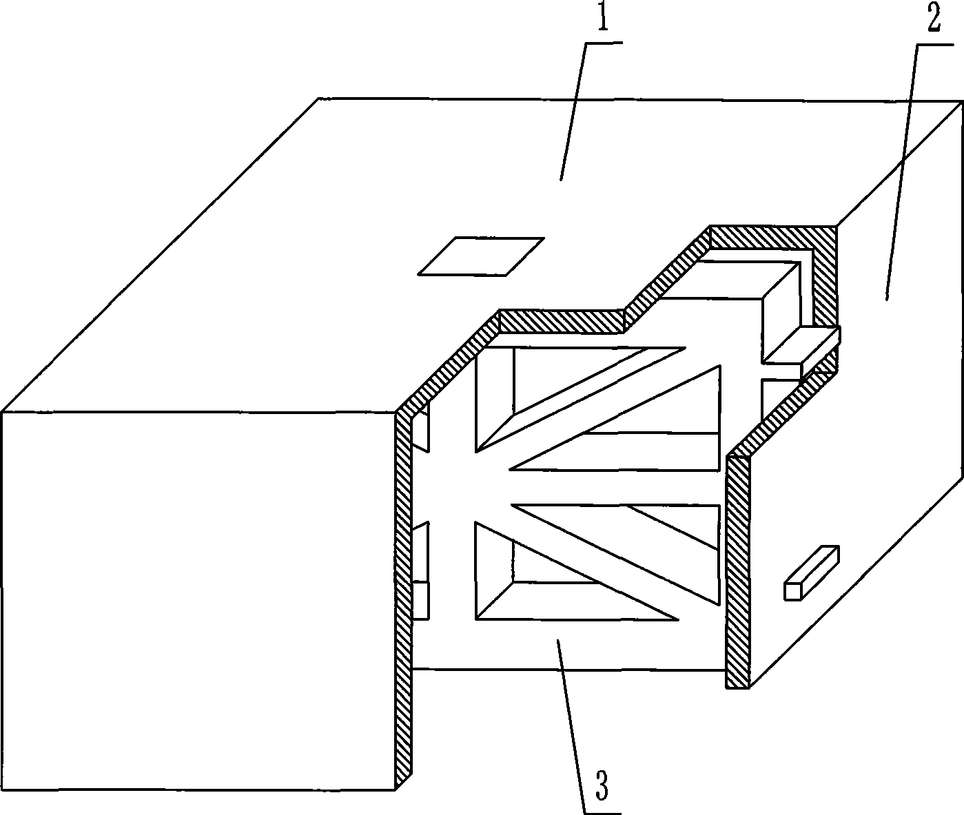
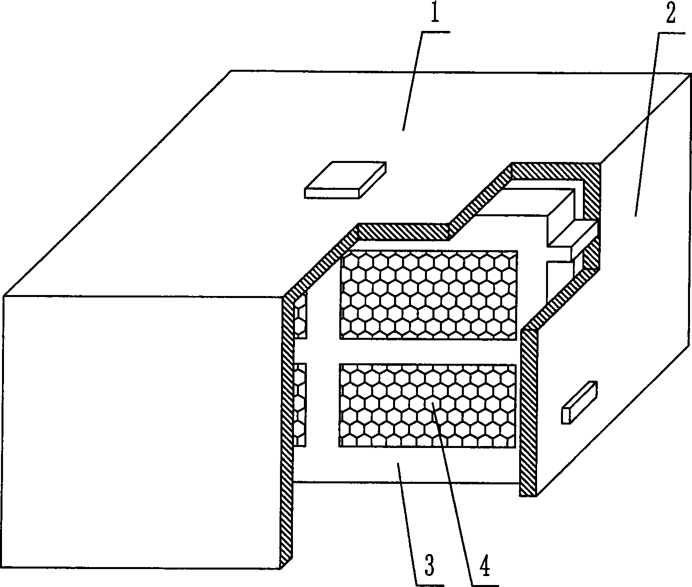
[0053] As shown in the accompanying drawings, the present invention includes an upper plate 1 and surrounding side walls 2, and the upper plate 1 and the surrounding side walls 2 form an open basin-shaped member, which is characterized in that the cavity of the basin-shaped member is provided with The stiffener 3 and the formwork components are provided with connecting pieces 28 connecting the formwork components to each other, and the connecting pieces 28 are socket rods and holes. In each accompanying drawing, 1 is an upper plate, 2 is a surrounding side wall, and 3 is a stiffening rib. In the following accompanying drawings, those with the same number have the same description. Such as figure 1 As shown, the upper plate 1 and the surrounding side walls 2 form an open basin-shaped member, and a stiffening rib 3 is arranged in the cavity of the basin-...
PUM
 Abstract
Description
Claims
Application Information
 - R&D
- Intellectual Property
- Life Sciences
- Materials
- Tech Scout
- Unparalleled Data Quality
- Higher Quality Content
- 60% Fewer Hallucinations
Browse by: Latest US Patents, China's latest patents, Technical Efficacy Thesaurus, Application Domain, Technology Topic, Popular Technical Reports.
© 2025 PatSnap. All rights reserved.Legal|Privacy policy|Modern Slavery Act Transparency Statement|Sitemap|About US| Contact US: help@patsnap.com