
Integral shift method for buildings

A building and overall technology, applied in the direction of building structure, construction, building maintenance, etc., can solve problems such as unsuitable permanent foundations, increased translational instability, and reduced building safety, so as to facilitate construction management and reduce in-transit Risk, the effect of short translation period

Active Publication Date: 2009-05-13
上海天演建筑物移位工程股份有限公司
View PDF0 Cites 30 Cited by
  • Summary
  • Abstract
  • Description
  • Claims
  • Application Information

AI Technical Summary

Problems solved by technology

Both solid steel rollers and concrete-filled steel tube rollers have their own advantages and disadvantages: steel rollers have high strength, are not easy to crush, have high rigidity, small deformation, small friction coefficient, and high recycling rate; Adaptive adjustments are made for changes in the clearance between the upper and lower slopes, and uneven force often occurs
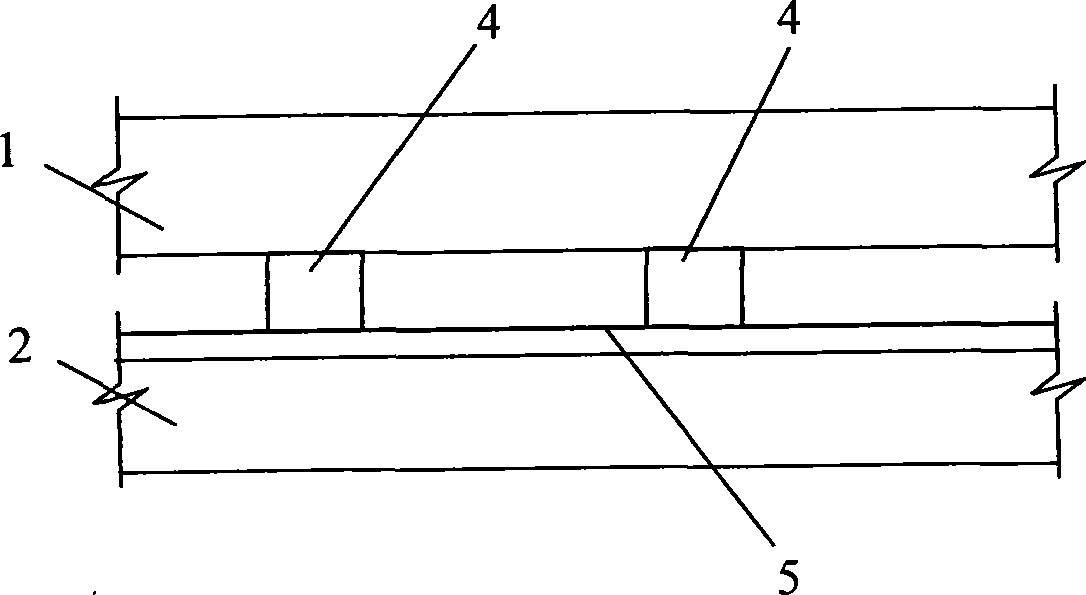
[0017] But the disadvantage is that the friction coefficient is relatively large, and the friction coefficient is between 0.12 and 0.15. Due to the difference in static and dynamic friction resistance, the acceleration change at startup is larger than that at rolling, and translation needs to provide a large jacking force. The required upper and lower beams and There are many reaction devices, and the total cost will increase; the requirements for the elevation and flatness of the sliding beam during construction are very high; when the sliding foot (that is, the support 4) is damaged due to excessive load, the design spacing of the sliding foot is generally Larger, it will double the support span of the upper sliding beam and the bearing capacity of adjacent sliding feet, which will lead to serious consequences
[0030] (3) The tilt of the upper pallet should not be used as a permanent foundation, which will reduce the long-term safety of the building
[0034] (3) A temporary slideway is required at the underground groove, which increases the instability of translation

Method used


Image

  • Integral shift method for buildings
  • Integral shift method for buildings
  • Integral shift method for buildings

Examples


Embodiment Construction

[0073] The overall shifting method of the building usually includes translation and jacking of the building.

[0074] Wherein, in the overall building displacement method described in the present invention, the translation of the building is to install a sufficient number of hydraulic jacks between the upper sliding beam supporting the building and the lower sliding beam as a slideway, and make the building move along with the building. The hydraulic jack slides on the slideway. During the sliding process, the building is kept stable by controlling the hydraulic pressure of the hydraulic jack at the corresponding position according to the flatness of the slideway surface.

[0075] Specifically, as Figure 6 As shown, a sufficient number of hydraulic jacks 7 are installed between the upper sliding beam 1 and the lower sliding beam 2, and the hydraulic jacks 7 are used as sliding feet, that is, the entire building is placed on several jacks, and the loads designed at each point ...


PUM


Abstract

The invention relates to an integral displacement method for a building, which comprises the steps of translating the building and jacking the building, wherein translating the building is to install hydraulic jacks with adequate quantity between an upper sliding beam which is used for supporting the building and a lower sliding beam which is used as a slideway, and to ensure that the building slides on the slideway along with the hydraulic jacks, and the building is kept steady by controlling hydraulic pressures of the hydraulic jacks at corresponding positions according to the level degree of the surface of the slideway during the sliding. The integral displacement method for the building overcomes the defects existing in the prior integral displacement method for the building, and has the advantages of ensuring that the building has steady movement, high movement speed and accurate movement; and the integral movement of the building by the method has low engineering cost, short period and high quality.

Description

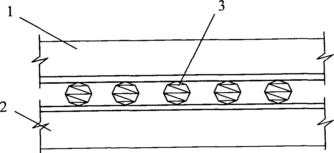
technical field [0001] The invention relates to a whole building shifting method for moving integral objects from an old address to a new address. Background technique [0002] Moving a building as a whole from an old site to a new site generally involves translating and jacking the building. [0003] At present, rolling translation and bearing sliding translation are mainly used for translation of buildings. [0004] Such as figure 1 As shown, the upper roller 3 is installed between the upper sliding beam 1 (upper slideway) and the lower sliding beam (slideway) 2, and the rolling translation is to use the roller 3 on the upper and lower sliding beam 1, 2 to move the building forward. Roller can adopt roller or roller, because the manufacturing cost of roller is higher, technical requirement is also higher, so what adopt at present mostly is roller. [0005] The roller materials include steel pipes, steel pipes filled with high-strength concrete in the middle, and solid ...

Claims


Application Information

Patent Timeline
IPC IPC(8): E04G23/06
Inventor 尹天军朱启华蓝戊已赵殿峰杨吾松董全保
Owner 上海天演建筑物移位工程股份有限公司
Learn More