
Flexible universal joint used for vehicle transmission shaft

A technology of transmission shafts and universal joints, applied in the direction of couplings, vehicle parts, elastic couplings, etc., can solve the problems of reducing the economic performance of the whole vehicle, large additional design costs, and small vibration reduction frequency range, and achieves improvement. Poor comfort, improved comfort issues, stable performance

Active Publication Date: 2010-09-08
CHERY AUTOMOBILE CO LTD
View PDF0 Cites 0 Cited by
  • Summary
  • Abstract
  • Description
  • Claims
  • Application Information

AI Technical Summary

Problems solved by technology

However, these redesigns often require a long design cycle and increase the additional design cost, and mainly have the disadvantages of too small frequency range of vibration reduction, increased weight and reduced economic performance of the vehicle, and unstable performance.

Method used


Image

  • Flexible universal joint used for vehicle transmission shaft
  • Flexible universal joint used for vehicle transmission shaft
  • Flexible universal joint used for vehicle transmission shaft

Examples


Embodiment 1

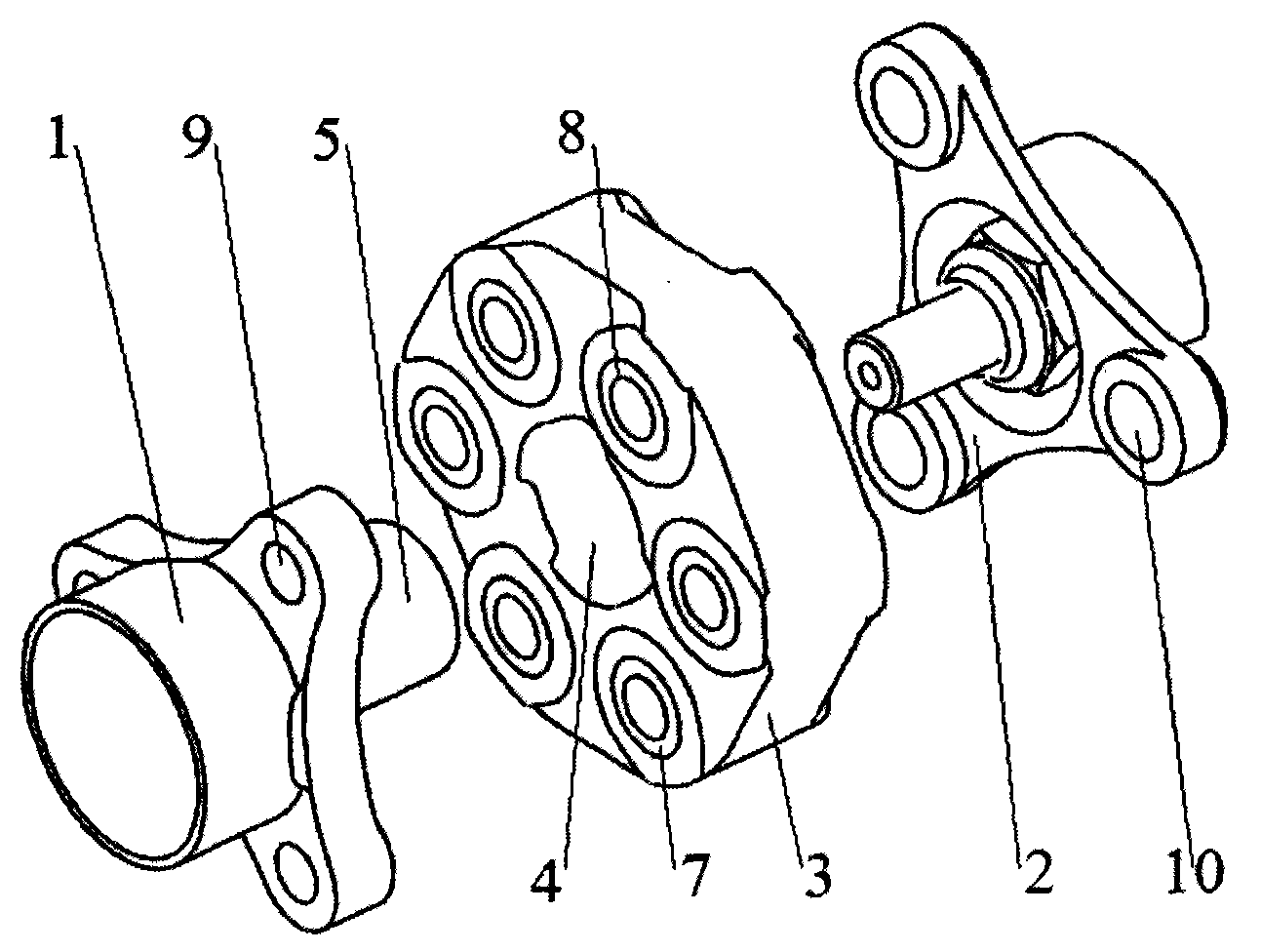
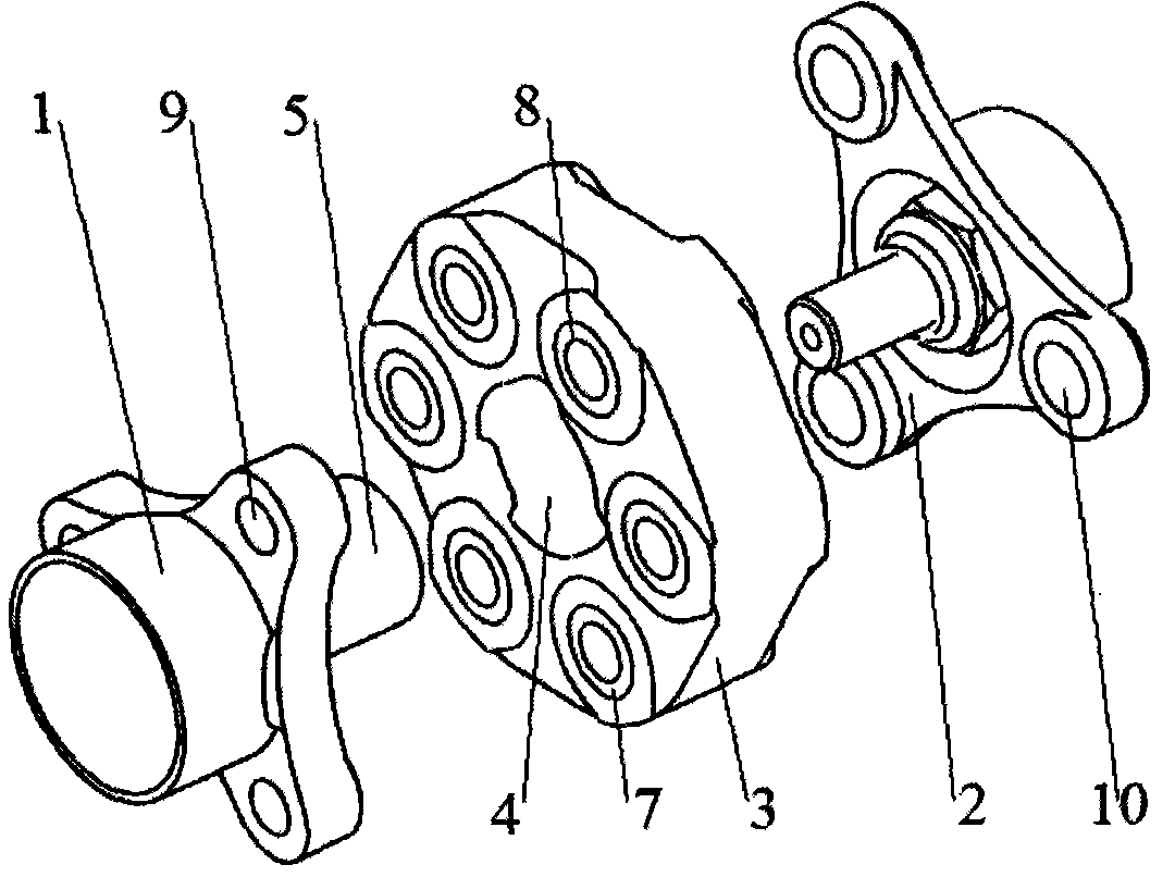
[0038] Embodiments of the connection structure between the flexible universal joint 3 and the transmission shaft flange 1 and the rear axle flange 2 according to the present invention:

[0039] 1. The flexible universal joint 3 is provided with an even number of universal joint connecting holes 8 uniformly distributed in the circumferential direction with its rotation axis as the center, parallel to the flexible universal joint 3 axis;

[0040] 2. The transmission shaft flange 1 and the rear axle flange 2 are respectively provided with a transmission shaft flange connection hole 9 and a rear axle flange connection hole 10 parallel to the universal joint connection hole 8. The number of the transmission shaft flange connection hole 9 and the rear axle flange connection hole 10 is half of the number of the universal joint connection hole 8;

[0041] 3. The flange connecting holes 9 of the transmission shaft and the flange connecting holes 10 of the rear axle are uniformly distri...

Embodiment 2

[0044] As shown in Figure 1, at the position where each transmission shaft flange connection hole 9 is connected to the universal joint connection hole 8, the rear axle flange 2 is a recess from the outer circumference to the center of the circle; The position where each rear axle flange connection hole 10 is connected to the universal joint connection hole 8, the transmission shaft flange 1 is a recess from the outer circumference to the center of the circle.

[0045] The purpose of setting the above-mentioned recesses is to prevent the connection between the transmission shaft flange 1 and the flexible universal joint 3 and the connection between the rear axle flange 2 and the flexible universal joint 3 from interfering with each other.

Embodiment 3

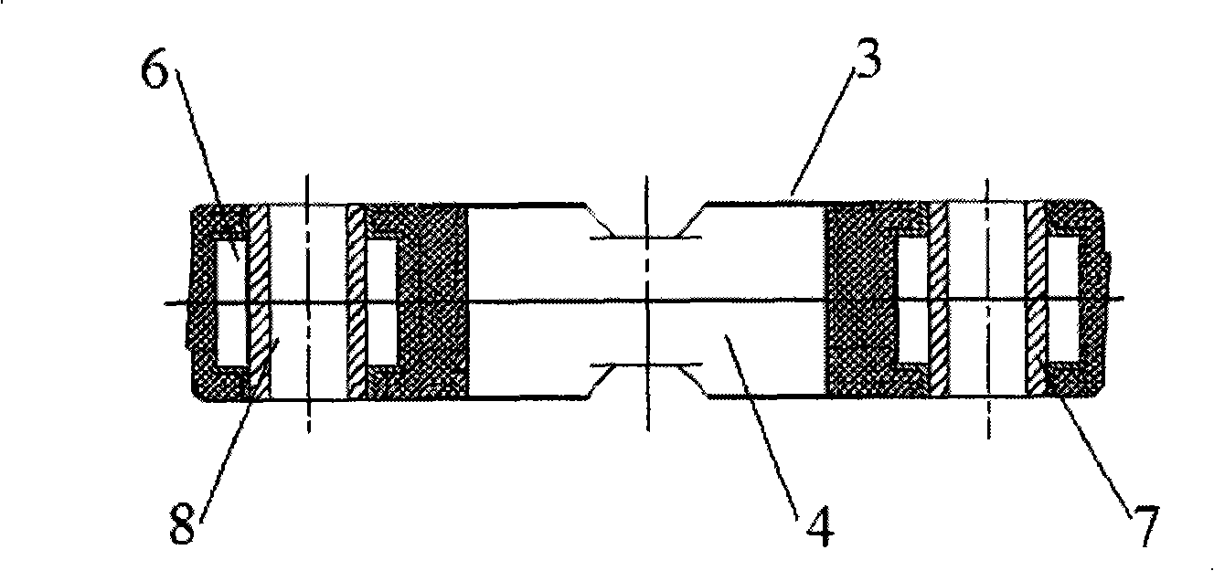
[0047] As shown in Figures 1 to 3, in the universal joint connection hole 8 of the present invention, a universal joint bush 7 made of a metal sleeve is provided, and the rubber material of the flexible universal joint 3 is After vulcanization, it is bonded to the universal joint bushing 7 as a whole, and the connecting piece passes through the inner hole of the universal joint bushing 7 .


PUM


Abstract

The invention discloses a flexible universal joint for an automobile transmission shaft, which is connected with a transmission shaft flange (1) and a rear axle flange (2). The axes of the transmission shaft flange (1) and the axes of the rear axle flange (2) are intersected and form an included angle. The flexible universal joint (3) is made of a rubber material, is arranged between the transmission shaft flange (1) and the rear axle flange (2) and is respectively connected with the transmission shaft flange (1) and the rear axle flange (2) through a connecting piece. By adopting the technical proposal, on the premise of reducing design cost and not prolonging design cycle as far as possible, the flexible universal joint can fully absorb the noise and vibration generated by a dynamic system, and does not reduce economic performance of an entire automobile because of additional weight added on the automobile, and has good manufacturing process property, and obtains vibration and noisereduction effects of the transmission shaft with stable performance.

Description

technical field [0001] The invention belongs to the technical field of automobile system construction, and relates to an automobile power transmission system. More specifically, the invention relates to a flexible universal joint for an automobile transmission shaft. Background technique [0002] An important indicator of automobile comfort performance is the noise and vibration of transmission parts. Due to the popularization of automobiles, drivers and passengers have higher and higher requirements for the comfort of automobiles. [0003] One problem in the drive shaft is that noise and vibration are easily transmitted and amplified. The noise and vibration transmitted from the powertrain of the vehicle during driving are transmitted to the rear axle assembly, and finally to the body through the chassis. [0004] Aiming at the above problems, the current typical solution is: add a noise damper to the shaft rod at the front end of the transmission shaft, such as the struct...

Claims


Application Information

Patent Timeline
Patent Type & Authority Patents(China)
IPC IPC(8): F16D3/16B60K17/22
Inventor 张文军
Owner CHERY AUTOMOBILE CO LTD
Learn More