LED electric torch

A technology of LED flashlight and LED lamp, which is applied in the field of flashlight, can solve the problems of circuit short circuit, flashlight flickering, unfavorable heat dissipation, etc., and achieve the effect of avoiding short circuit and compact internal structure

Active Publication Date: 2010-08-25
宁波双鹿电气有限公司
View PDF0 Cites 0 Cited by
  • Summary
  • Abstract
  • Description
  • Claims
  • Application Information

AI Technical Summary

Problems solved by technology

But at the same time, there are still some shortcomings in the structure of the current LED flashlight: 1. The overall structure of the flashlight is not compact enough, and the vibration of the flashlight during use is likely to cause damage to the LED lamp and components or cause a short circuit in the circuit, resulting in the failure of the flashlight to work normally.
2. The negative pole of the power supply and the shell of the flashlight are often in poor contact, causing the flashlight to flicker.
3. High-power LEDs generate a lot of heat during work, and the structure of existing LED flashlights is not conducive to the dissipation of heat
But this flashlight has the following disadvantages at the same time: 1 or 2 battery flashlights are simply boosted, the battery voltage drops with the increase of the flashlight usage time, the working current of the LED lamp drops with the battery voltage drop, and the low current makes the LED The lamp cannot work effectively or even not light up. At this time, the remaining energy in the battery cannot be fully utilized, resulting in a low utilization rate of the battery and unnecessary waste of energy.

Method used


Image

  • LED electric torch
  • LED electric torch
  • LED electric torch

Examples


Embodiment Construction

[0020] The present invention will be further described in detail below in conjunction with the accompanying drawings and embodiments.

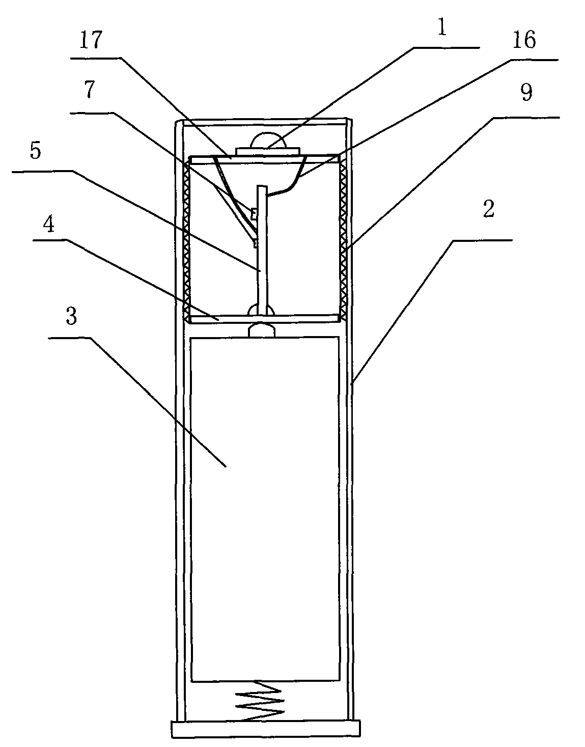
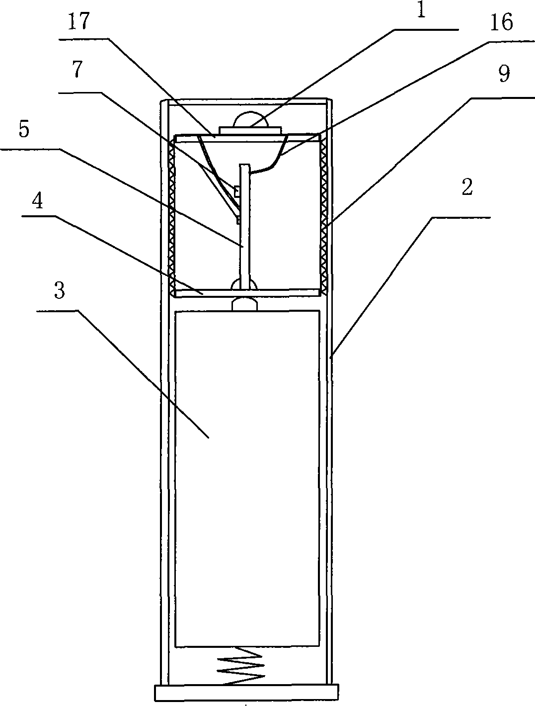
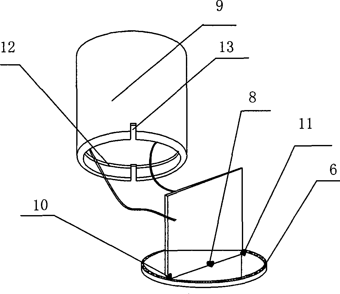
[0021] An LED flashlight, including an LED lamp 1, a metal barrel body 2, a control circuit board and a dry battery 3, a metal sleeve 9 is arranged inside the metal barrel body 2, and the control circuit board includes a first PCB circuit board 4 and a second PCB circuit board 5. The periphery of the first PCB circuit board 4 is provided with a negative wiring 6, and the middle of the first PCB circuit board 4 is provided with a positive wiring (not shown in the figure), and the components 7 of the control circuit are arranged on the second PCB circuit board 5, The high-power LED lamp 1 is arranged on the aluminum substrate 17 , the aluminum substrate 17 seals one end of the metal sleeve 9 , and the edge of the aluminum substrate 17 is in close contact with the inner wall of the metal sleeve 9 . The LED lamp 1 is connected to the control circu...


PUM


Abstract

The invention discloses an LED flashlight which comprises an LED lamp, a metal stack shell, a control circuit board and a dry battery, wherein, the metal stack shell is internally provided with a metal sleeve, the control circuit board includes a first PCB and a second PCB which is vertically fixed on the first PCB, and the first PCB and the second PCB are arranged in a T shape; the second PCB extends into the metal sleeve, the LED lamp is arranged at one end of the metal sleeve, and the other end of the metal sleeve is sealed by the first PCB; anode wiring of the first PCB is connected with anode of the dry battery, and cathode wiring of the first PCB is connected with the metal sleeve; the LED flashlight has the advantages that the internal structure is compact, the control circuit board is positioned in the metal sleeve, components and parts on the circuit board are not damaged by the shake in the using process, and the short pass is avoided.

Description

technical field [0001] The invention relates to a flashlight, in particular to an LED flashlight. Background technique [0002] The traditional flashlight is generally powered by two No. 1 dry batteries, and the luminous part is a light bulb. Its disadvantages are that it is relatively large in size and weight, consumes a lot of power, and is inconvenient to carry. With the advancement of technology, LED flashlights with small size and low power consumption have appeared. There is an LED flashlight, which comprises a lamp holder with an LED lamp, a barrel body and a tail cap, and a control circuit board and a dry battery are respectively arranged in sequence in the barrel body. In the structure of the flashlight, the LED light is connected to the control circuit board through wires, the positive input terminal of the control circuit board is connected to the positive terminal of the dry battery, and the negative terminal of the dry battery is connected to the tail cover of ...

Claims


Application Information

Patent Timeline
Patent Type & Authority Patents(China)
IPC IPC(8): F21L4/00F21V15/02F21V17/00F21V23/00F21Y101/02F21Y115/10
Inventor 顾忠良胡浩峰胡双有
Owner 宁波双鹿电气有限公司
Why Eureka
Try Eureka