Refrigerant distributor used for air conditioner heat-exchanger

A refrigerant distributor and heat exchanger technology, applied in the direction of refrigerators, refrigeration components, refrigeration and liquefaction, etc., can solve the problems of not being able to ensure the uniformity of the gas-liquid two-phase, affecting the mute effect of the air conditioner, and reducing the gas-liquid two-phase equalization, Achieve the effect of avoiding refrigerant pulsation and impact sound, avoiding capillary blockage, and reducing separation

Inactive Publication Date: 2009-05-13
GUANGDONG MIDEA ELECTRIC APPLIANCES CO LTD
View PDF0 Cites 14 Cited by
  • Summary
  • Abstract
  • Description
  • Claims
  • Application Information

AI Technical Summary

Problems solved by technology

[0002] At present, the refrigerant distributors used in air-conditioning heat exchangers are built-in distributors or ordinary barrel-shaped distributors. The structure of the built-in distributor is as follows: figure 1 As shown, the flow rate of the refrigerant can be increased through the small-aperture gasket embedded in the middle, thereby reducing the separation of the gas-liquid two-phase, weakening the influence of gravity, and making the refrigerant split evenly. The cavity is small, and there is obvious refrigerant pulsation sound during the operation of the air conditioner, which seriously affects the quiet effect of the air conditioner; ordinary barrel-shaped distributors such as figure 2 As shown, although the cost is cheap, the process is simple, and it has a large mixing chamber, due to the large diameter of the input pipe, the uniformity of the gas-liquid two-phase cannot be ensured, and there are high requirements for the installation angle, which generally needs to be placed vertically

Method used


Image

  • Refrigerant distributor used for air conditioner heat-exchanger
  • Refrigerant distributor used for air conditioner heat-exchanger
  • Refrigerant distributor used for air conditioner heat-exchanger

Examples


Embodiment

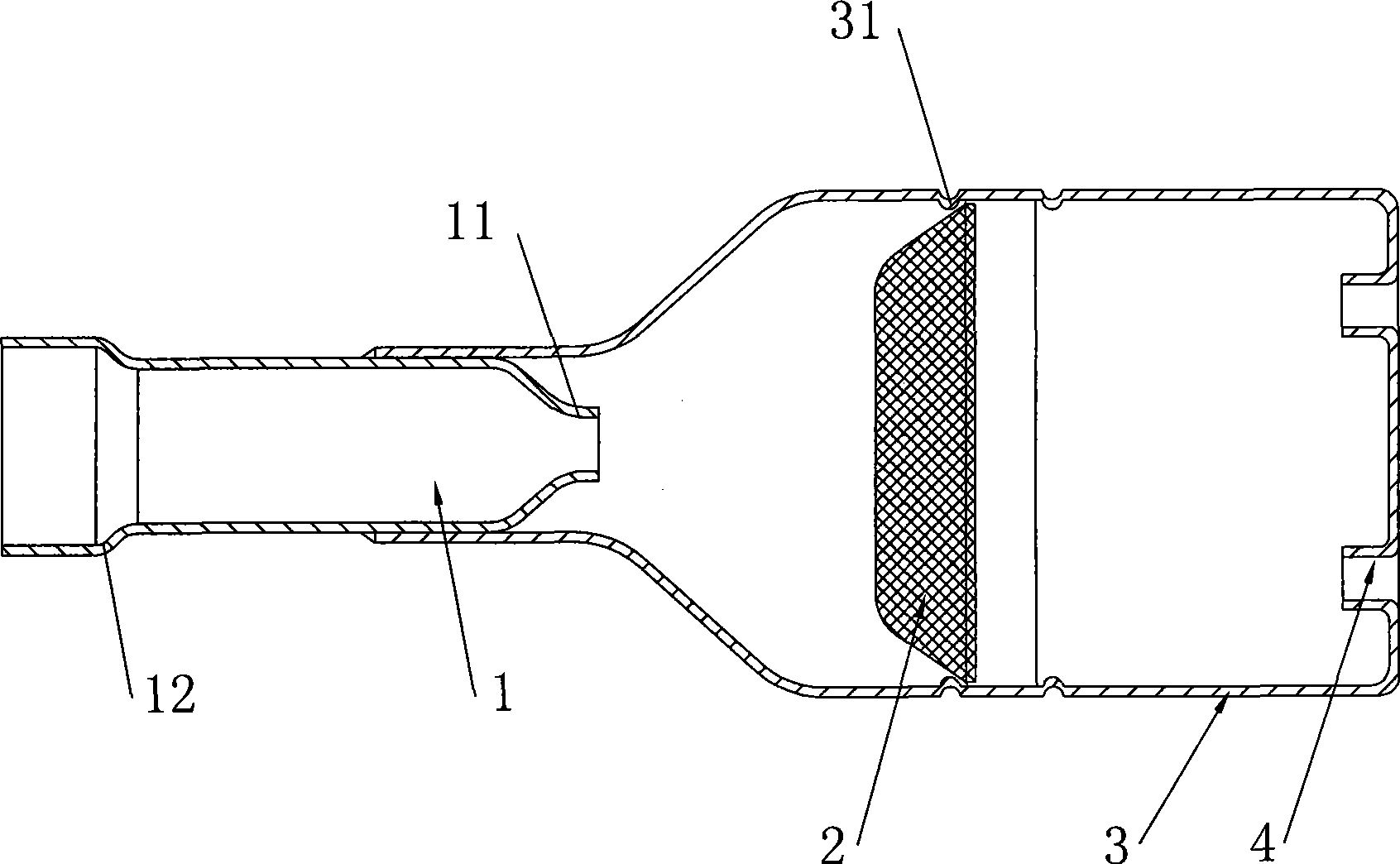
[0015] Such as image 3 , 4 As shown, the refrigerant distributor of the present invention for air-conditioning heat exchangers includes a housing 3 and an input pipe 1 welded on its input end. The output end of the housing 3 is provided with a number of distribution holes 4, wherein the input pipe 1. The nozzle 11 extending into the input end of the housing 3 adopts the form of a tapered mouth, and its diameter is smaller than that of the inlet end 12. A filter screen 2 is installed in the cavity of the housing 3. In this embodiment, the above-mentioned filter screen 2 is installed in the middle of the cavity of the housing 3, the bottom of the screen faces the input end, and the straight section of the screen mouth sticks to the inner wall of the housing 3 and is clamped on two annular protrusions. 31 formed in the shallow groove.

[0016] In this embodiment, the housing 3 is in the shape of a wine bottle, and the diameter of the input end is smaller than the diameter of t...


PUM


Abstract

The invention relates to a refrigerant distributor used in an air-conditioning heat exchanger. The refrigerant distributor comprises a shell and an input tube welded on an input end of the shell, and a plurality of relief holes are arranged on an output end of the shell. The refrigerant distributor is characterized in that the orifice of the input tube which extends into the input end of the shell takes a tapered shape, the diameter of the orifice is less than that of the input end, and a filter screen is arranged in the cavity of the shell. The refrigerant distributor adopts a structure including a tapered jet-type input tube and the filter screen arranged in the cavity of the shell, which can avoid fluid resistance loss and impact vibration caused by abrupt change of cross section, greatly increase flow rate of the refrigerant, and reduce separation of gas and liquid phases, reduce effect of gravity so as to cause uniform refrigerant flow distribution, and also avoid requirement for a mounting angle; furthermore, the filter screen which is arranged in the cavity of the shell can filter off impurities and avoid blocking of capillary tubes, and can divide big air bubbles generated by flash evaporation into small bubbles, which prevents pulsation and impulsive sound of the refrigerant generated by air bubble cracking and greatly reduces the running noise. Therefore, the refrigerant distributor combines the advantages of built-in distributors and common tubby distributors very well.

Description

Technical field: [0001] The invention relates to a refrigerant distributor for an air-conditioning heat exchanger, which belongs to the improvement technology of the refrigerant distributor. Background technique: [0002] At present, the refrigerant distributors used in air-conditioning heat exchangers are built-in distributors or ordinary barrel-shaped distributors. The structure of the built-in distributor is as follows: figure 1 As shown, the flow rate of the refrigerant can be increased through the small-aperture gasket embedded in the middle, thereby reducing the separation of the gas-liquid two-phase, weakening the influence of gravity, and making the refrigerant split evenly. The cavity is small, and there is obvious refrigerant pulsation sound during the operation of the air conditioner, which seriously affects the quiet effect of the air conditioner; ordinary barrel-shaped distributors such as figure 2 As shown, although the cost is cheap, the process is simple, a...

Claims


Application Information

Patent Timeline
IPC IPC(8): F25B41/00
Inventor 吴彦东游斌李苏洋郭军莫平辉李仕云
Owner GUANGDONG MIDEA ELECTRIC APPLIANCES CO LTD
Why Eureka
Try Eureka