
Electrohydrodynamic (EHD) refrigerant pump

Active Publication Date: 2017-03-30
WORCESTER POLYTECHNIC INSTITUTE
View PDF2 Cites 0 Cited by
  • Summary
  • Abstract
  • Description
  • Claims
  • Application Information

AI Technical Summary

Benefits of technology

This patent describes a way to improve the efficiency of cooling systems by using an electrohydrodynamic (EHD) pump to increase the flow rate and pressure of refrigerant in a vapor compression system. This allows for the use of a smaller compressor, reducing energy usage. The EHD pump works by inducing a flow of liquid refrigerant through the use of electrodes, which results in a pumping mechanism that is more energy efficient than conventional compressors. Overall, this approach provides a more energy efficient and efficient cooling system.

Problems solved by technology

Unfortunately, conventional approaches to efficiency in vapor compression cooling systems focus on compressor improvements, and do not leverage the observation that compressing a fluid in a gas phase is very energy intensive compared to pumping a liquid.
Further, conventional approaches cannot pump a liquid film when it occurs in a combined fluidic flow with a gaseous counterpart.

Method used


Image

  • Electrohydrodynamic (EHD) refrigerant pump
  • Electrohydrodynamic (EHD) refrigerant pump
  • Electrohydrodynamic (EHD) refrigerant pump

Examples


Embodiment Construction

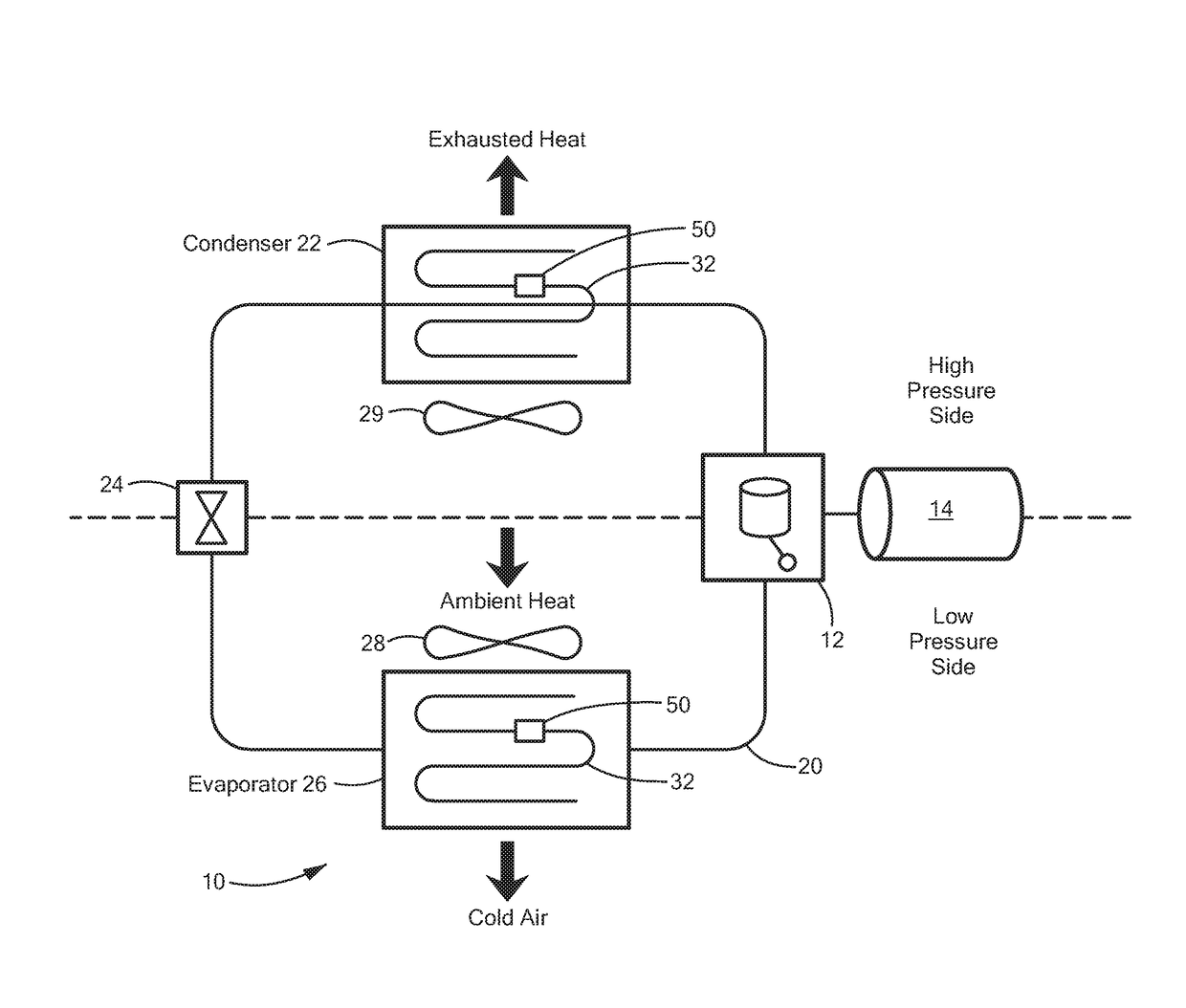
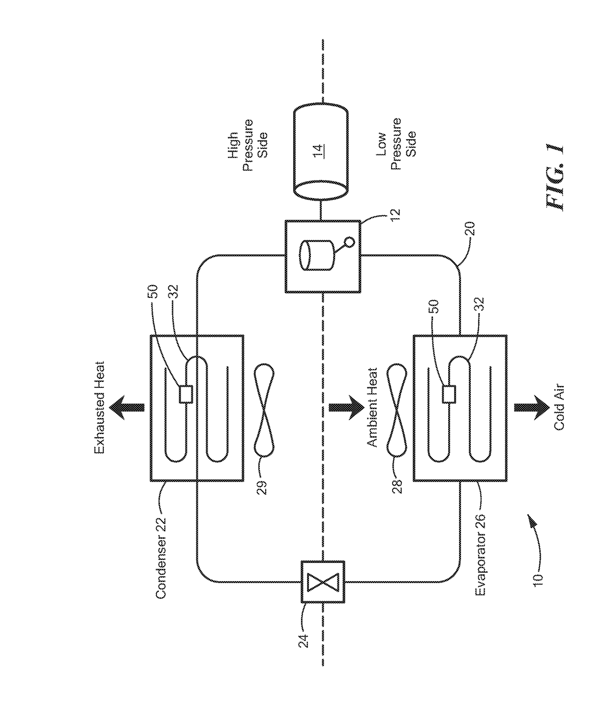
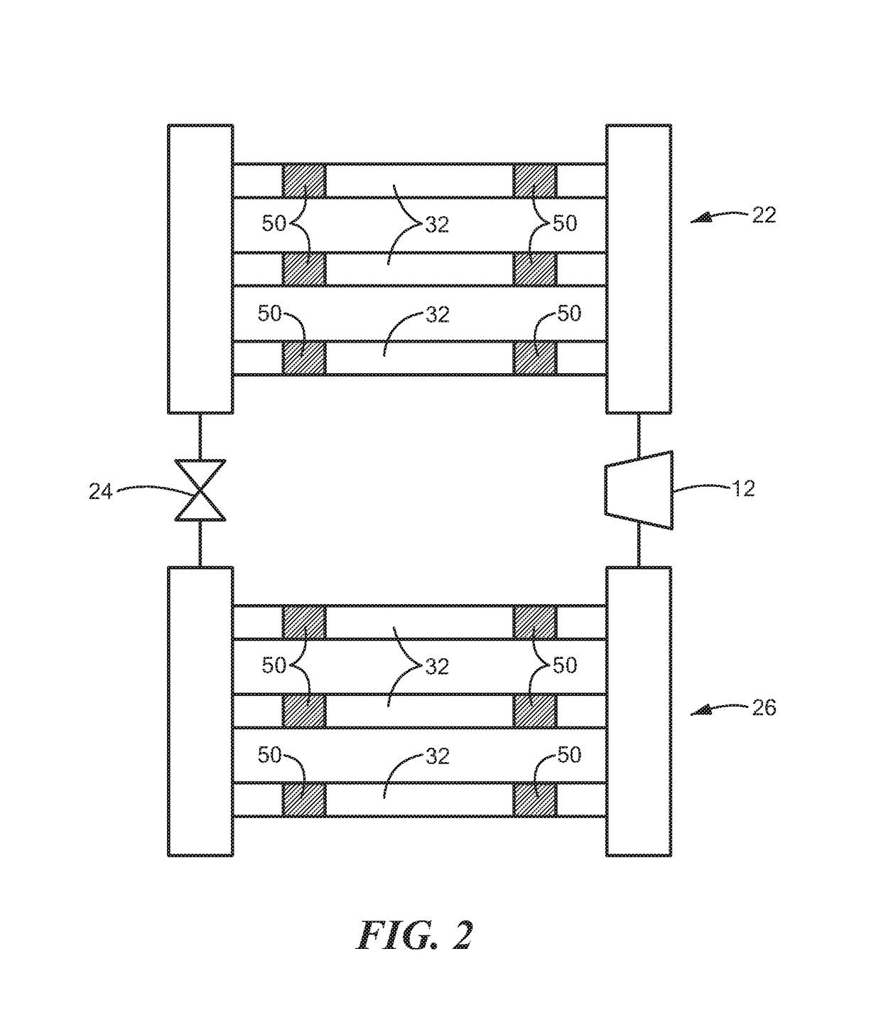
[0013]Depicted below is an example of a vapor compression cooling system suitable for use with configurations herein. The system components include the compressor, evaporator and condenser including refrigerant vessels, expansion device and associated refrigeration tubing suitable for transporting the pressurized refrigerant. The refrigerant travels in a circuitous path with EHD pumps disposed in the vessels through the thermal exchange components: evaporator and condenser. The disclosed configuration depicts an example usage of the claimed EHD pumps; alternative refrigerant based transport, or placement outside the condenser and evaporator may be performed in alternate configurations.

[0014]EHD phenomena involve the interaction of electric fields and flow fields in a dielectric fluid medium. The EHD conduction pumping mechanism is associated with heterocharge layers of finite thickness in the vicinity of the electrodes, which are based on the process of dissociation of the neutral e...


PUM


Abstract

An electrohydrodynamic (EHD) pump increases refrigerant flow rate and the resulting pressure in a vapor compression based cooling system for permitting reduced compressor sizes and power demands. The EHD pump disposes electrodes in a liquid path of the refrigerant flow, and increases fluid flow and resulting pressure by an induced liquid flow between a pair of asymmetric electrodes. Voltage applied to these electrodes results in a conduction pumping mechanism associated with heterocharge layers in the vicinity of the electrodes based on disassociation of a neutral electrolyte species in the refrigerant fluid and recombination of the generated ions. The induced flow draws the liquid due to a net fluid flow toward one of the electrodes based on the asymmetry of the electrode pair. Electrodes are disposed on an inner surface of a refrigerant vessel, in communication with an annular liquid film that forms around the inner circumference in two-phase fluid systems.

Description

RELATED APPLICATIONS:[0001]This application claims the benefit under 35 U.S.C. §119(e) of U.S. Provisional Patent Application No. 62 / 234,092, filed Sep. 29, 2015, entitled “ELECTROHYDRODYNAMIC (EHD) REFRIGERANT PUMP,” incorporated herein by reference in entirety.STATEMENT REGARDING FEDERALLY SPONSORED RESEARCH AND DEVELOPMENT[0002]The subject matter disclosed herein was developed from funding under contract No. NNX12AR32G with NASA (National Aeronautics and Space Administration). The Government has certain rights in the Invention.BACKGROUND[0003]Vapor compression systems are employed for refrigeration and cooling for ambient air (“air conditioning”) systems and for refrigeration / freezing for perishable food items. Such vapor compression systems generally rely on a two-phase refrigerant that alternates gaseous and liquid states in a cyclic manner to transfer heat from a cooled or conditioned region and exhaust the heat to the ambient outside surroundings. A compressor alters the pres...

Claims


Application Information

Patent Timeline
IPC IPC(8): F25B1/10H02N11/00F25B31/00
CPCF25B1/10H02N11/006F25B31/00F04B19/006F25B1/00F28F2250/08F04B17/00H02K44/04H02K44/02
Inventor YAGOOBI, JAMAL S.
Owner WORCESTER POLYTECHNIC INSTITUTE
Learn More