High-power LED packaging and die bonding method

A LED packaging and high-power technology, which is applied in semiconductor/solid-state device manufacturing, electrical components, circuits, etc., can solve problems that are difficult to meet large-scale, stable and reliable production requirements, dispensing uniformity, and unsatisfactory glue volume. High cost of materials and other issues, to achieve the effect of stable and reliable dispensing quality, stable and reliable quality, and high production efficiency

Active Publication Date: 2009-05-13
SHENZHEN BANG BELL ELECTRONICS
View PDF0 Cites 12 Cited by
  • Summary
  • Abstract
  • Description
  • Claims
  • Application Information

AI Technical Summary

Problems solved by technology

[0009]However, the eutectic alloy currently used for LED chip bonding is mainly AuSn alloy, and the material cost is high
The eutectic solder paste particles are larger than ordinary thermally conductive adhesives, and the viscosity is also higher. However, in the current die-bonding operation, the existing dispensing head used for dipping the glue is small and sharp (such as figure 1 As shown), when dispensing solder paste with existing dispensing equipment and dispensing methods, the dispensing uniformity and glue volume are not ideal, and it is difficult to meet the large-scale, stable and reliable production requirements

Method used


Image

  • High-power LED packaging and die bonding method
  • High-power LED packaging and die bonding method
  • High-power LED packaging and die bonding method

Examples


Embodiment Construction

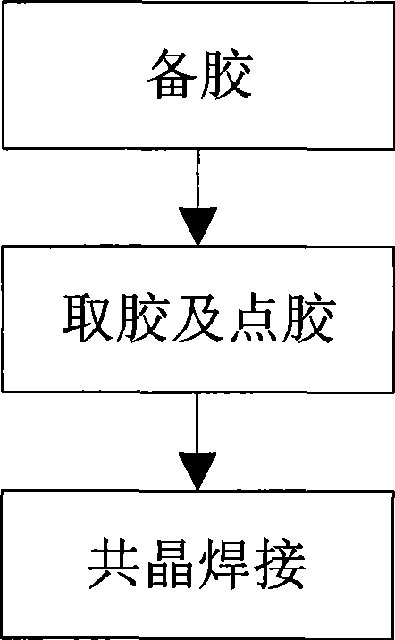
[0023] Such as figure 2 As shown, the present invention provides a high-power LED package die-bonding method, comprising the following steps:

[0024] In the glue preparation step, put eutectic solder paste as a solid crystal material in the glue tray, and the eutectic solder paste can use a variety of common solder pastes, such as any one of the following solder pastes: Sn 96.5 Ag 3.0 Cu 0.5 , Sn 95.5 Ag 4.0 Cu 0.5 , Sn 96.5 Ag 3.5 , Sn 63 Pb 37 , Sn 42 Bi 58 , the surface of the solder paste on the part where the glue is to be taken is smoothed by the scraper of the rubber plate;

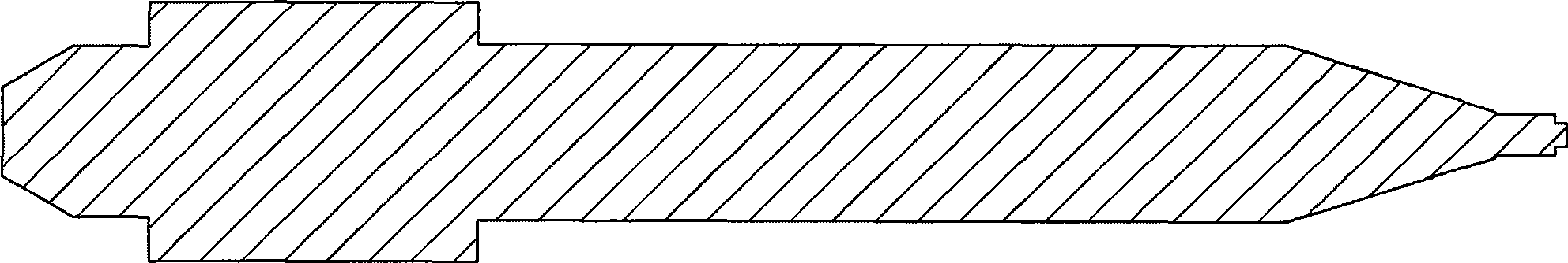
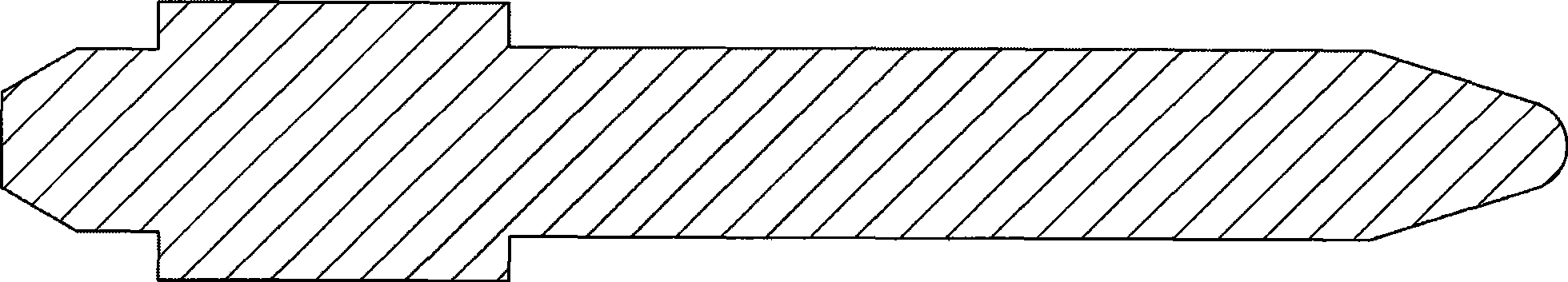
[0025] In the glue taking and dispensing steps, use a blunt dispensing head to dip the solder paste from the glue tray, and then attach the removed solder paste to the base to fix the LED chip's solid crystal position;

[0026] In the eutectic soldering step, place the LED chip with a metal layer on the bottom surface at the crystal-bonding position with solder paste on the base, and ...


PUM


Abstract

The invention relates to a high-power LED packaging and crystal fixing method, comprising the following steps: preparing a glue: an eutectic solder paste is put in a plastic plate, and a scraper of the plastic plate is used for leading the surface of the solder paste at the glue taking part to be smooth; taking the glue and dispensing the glue: a glue dispensing head with a blunt head is utilized to dip the solder paste from the plastic plate and the taken solder paste is dispensed at the crystal fixing position on a base; eutectic welding: an LED chip with a metal layer at the bottom surface is arranged at the crystal fixing position with the solder paste, and the temperature is increased to the eutectic temperature after the compaction, thereby leading the metal on the bottom surface of the LED chip and the base to realize the eutectic welding by the solder paste. The thermal conductivity of the eutectic solder paste which is adopted by the method is equal to AuSn, thereby being capable of effectively solving the high-power heat dissipation problem and the mechanical strength problem; in addition, the glue dispensing head with the blunt head is matched for use, thereby being capable of effectively ensuring the glue dispensing quality to be stable and reliable.

Description

technical field [0001] The invention relates to the field of LED packaging, in particular to a high-power LED packaging crystal bonding method. Background technique [0002] In the LED packaging process, a die-bonding step of fixing the LED chip to the base needs to be performed first. Depending on the power of the LED and the type of package, the die-bonding materials and die-bonding methods used are also different. At present, the power of the general in-line LED is about 0.066W. The heat emitted by the LED can be dissipated through the positive and negative metal pins. The problem of heat can be ignored, so the use of insulating glue is enough. The power of the piranha package is generally below 0.5W, and multiple low-power chips are usually packaged in a combined package, through a large area of ​​positive and negative pins and circuit boards, and then low thermal conductivity silver glue (thermal conductivity is generally less than 5w) / m·k) can solve the heat problem...

Claims


Application Information

Patent Timeline
Patent Type & Authority Applications(China)
IPC IPC(8): H01L33/00H01L21/50H01L21/58H01L33/52
Inventor 李盛远
Owner SHENZHEN BANG BELL ELECTRONICS
Why Eureka
Try Eureka