D/A signal superposition feedback circuit

A technology of signal superposition and feedback circuit, which is applied in the direction of electric light sources, electrical components, and adjustment of electrical variables, etc., can solve problems such as the inability to ensure reliable and stable operation of single-chip microcomputers, characteristic jumps in the steady-state stage of lamp tubes, and bad electronic ballasts, etc.

Inactive Publication Date: 2012-06-20
合肥微纳电工有限公司
View PDF0 Cites 0 Cited by
  • Summary
  • Abstract
  • Description
  • Claims
  • Application Information

AI Technical Summary

Problems solved by technology

In the starting stage, the lamp tube presents a negative resistance characteristic, that is, in this stage, the lamp current gradually decreases, the voltage gradually increases, and the power gradually increases; when both the current and voltage reach the rated value, it enters the steady state stage. During this period, the lamp tube presents positive resistance characteristics. In this stage, the current and voltage are in a proportional relationship, that is, they increase or decrease at the same time. However, there are also characteristic jumps in the lamp tube steady state stage, which requires the electronic ballast to be able to At the same time, it meets the load characteristic requirements of the starting phase and the steady state phase
[0003] The load characteristic of the high-intensity gas discharge lamp puts forward quite high requirements on the control part of the electronic ballast: in the ignition stage, the ballast provides a stable current to heat the gas in the lamp tube and raise the lamp voltage; In the steady-state stage, constant power control must be achieved, because the consistency of high-intensity gas discharge lamps is very poor, and the steady-state voltage and current of lamps from different manufacturers and batches often vary greatly, which will affect the quality of the lamps. Steady-state power, shorten lamp life
If a general-purpose PWM control chip is used, the characteristics of the two working stages cannot be satisfied at the same time, and if an MCU is used for control, due to the harsh working environment of the electronic ballast, the reliable and stable operation of the single-chip microcomputer cannot be guaranteed. The whole system crashes
Among the various high-intensity discharge lamp electronic ballasts currently on the market, the core control parts of mainstream products all use dedicated chips, and these dedicated chips all have defects in stability and functional integrity to varying degrees.

Method used


Image

  • D/A signal superposition feedback circuit
  • D/A signal superposition feedback circuit
  • D/A signal superposition feedback circuit

Examples


Embodiment

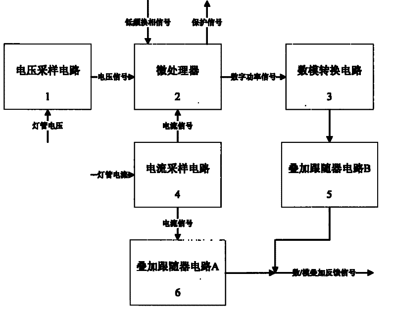
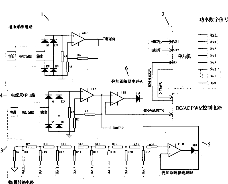
[0025] see image 3 The voltage sampling circuit 1 includes a voltage transformer, and its secondary is connected to a full-bridge rectifier. The full-bridge rectifier is composed of diodes D6-D9. The operational amplifier U1C and resistors R4-R6 form an amplifier circuit to obtain a DC voltage signal and send it to the microcontroller. AD1 port. The current sampling circuit 4 includes a current transformer, and its secondary is connected to a full-bridge rectifier. The full-bridge rectifier is composed of diodes D1-D4, an operational amplifier U1A and resistors R1-R3 to form an amplifier circuit, and the obtained DC current signal is sent to the AD2 port of the single-chip microcomputer. , while also entering the superposition follower circuit A6. The superposition follower circuit A6 is composed of the operational amplifier U1B and the diode D5, the output terminal of the operational amplifier U1B is connected to the anode of the diode D5, and the cathode of the diode D5 is...


PUM


Abstract

The present invention relates to digital / analog signal superposition feedback circuit, and is applied to circuit of high strength gas discharge lamp electronic ballast, which comprises the following components: voltage sampling circuit, current sampling circuit, digital / analog conversion circuit, superposition follower circuit and microprocessor. The invention comprises the following steps: sampling circuit transmits signal of lamp voltage and current to microprocessor by multiply for calculating power; digital power signal output by microprocessor is converted into corresponding analog signal and transmitted to superposition follower circuit B; meanwhile sampled current signal gets into superposition follower circuit A; superposition follower circuit A and B output digital / analog superposition feedback signal together. Analog signal and digital signal of current and power of characterization lamp can be compensated mutually and output superposing, and characteristic demand of lamp starting and constant power output of after stable can be realized.

Description

technical field [0001] The invention relates to a circuit in an electronic ballast, in particular to a circuit in an electronic ballast for a high-intensity gas discharge lamp. Background technique [0002] High-intensity gas discharge has high lighting efficiency and good color rendering, and has been widely used in various lighting occasions, and its matching electronic ballasts have also developed accordingly. High-intensity discharge lamps have unique electrical characteristics, which can be divided into two operating phases: the glow phase and the steady-state phase. In the starting stage, the lamp tube presents a negative resistance characteristic, that is, in this stage, the lamp current gradually decreases, the voltage gradually increases, and the power gradually increases; when both the current and voltage reach the rated value, it enters the steady state stage. During this period, the lamp tube presents positive resistance characteristics. In this stage, the curre...

Claims


Application Information

Patent Timeline
Patent Type & Authority Patents(China)
IPC IPC(8): H05B41/36H05B41/288G05F1/10G05B19/02
CPCY02B20/202Y02B20/00
Inventor 余晓东
Owner 合肥微纳电工有限公司
Why Eureka
Try Eureka