

Gas separation membrane
A gas separation membrane and gas separation technology, applied in separation methods, semi-permeable membrane separation, dispersed particle separation, etc., can solve problems such as gas performance degradation, and achieve the effect of high oxygen permeation rate and high oxygen and nitrogen selectivity
- Summary
- Abstract
- Description
- Claims
- Application Information
AI Technical Summary
Problems solved by technology
Method used
Image

Examples
Embodiment
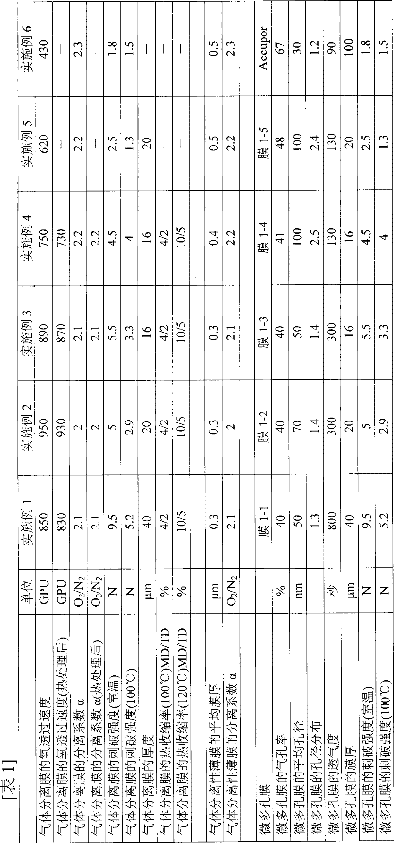
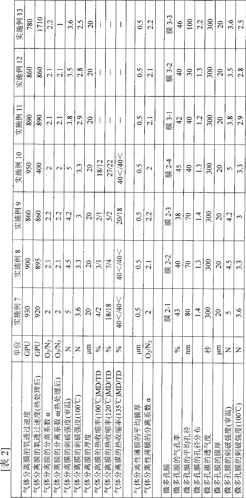
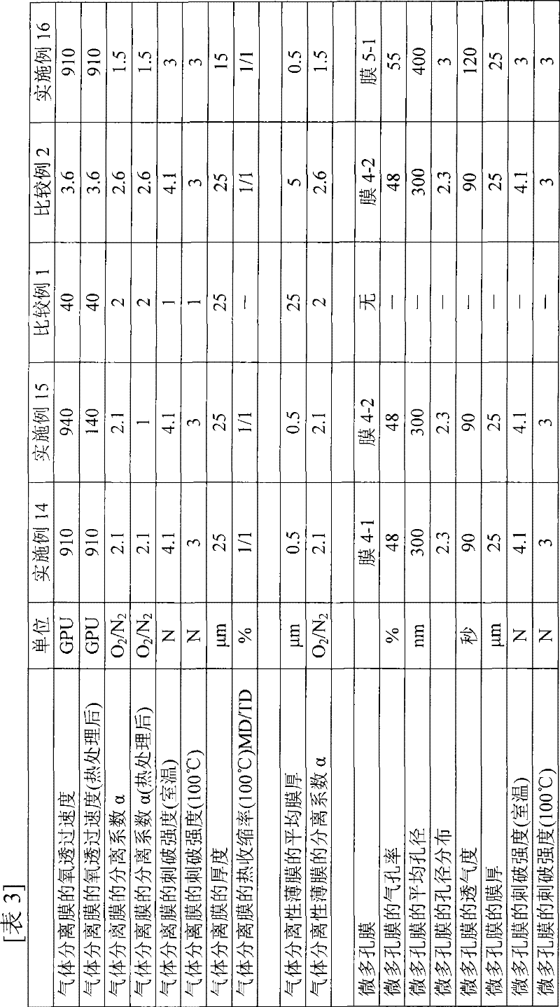
[0117] Hereinafter, the present invention will be described more specifically using examples and the like, but the present invention is not limited by these examples and the like. Furthermore, the test methods and processing methods for the properties given in Examples and Comparative Examples are as follows.
[0118] (1) Observation conditions of scanning electron microscope (SEM)
[0119] Scanning electron microscope (SEM) observation was performed under the following conditions.
[0120] Sample: Cut the microporous membrane into an appropriate size, fix it on the sample stage, and apply Os with about 6nm as a sample for microscopic examination.
[0121] Device: HITACHI S-4700
[0122] Acceleration voltage: 1kV
[0123] MODE: Ultra High Resolution
[0124] Detector: Upper
[0125] (2) Surface structure of microporous membrane
[0126] According to the condition of (1), the surface structure was determined by scanning electron microscope (SEM) observation.
[0127] (3)...
reference example 1-2
[0193] 95 parts by weight of high-density polyethylene (viscosity average molecular weight: 280,000), 5 parts by weight of polypropylene (viscosity average molecular weight: 250,000), and 0.3 parts by weight of antioxidant were mixed. This mixture was fed into a twin-screw extruder through a feeder. Further, 100 parts by weight of liquid paraffin (dynamic viscosity at 37.78°C: 75.9cSt) was injected into the extruder by side feeding, and melt kneading was performed at 200°C. After the obtained polymer gel was extruded from the T-die provided at the front end of the extruder, it was immediately cooled and solidified with a casting roll cooled to 25° C. to form a film with a thickness of 1.3 mm.
[0194] This sheet was simultaneously stretched to 7×7 times at 120° C. with a biaxial stretcher. Then, this stretched sheet was immersed in methyl ethyl ketone, and the liquid paraffin was removed by extraction, followed by drying to obtain a microporous membrane. Further, it was heat...
reference example 1-3
[0196] 7 parts by weight of ultra-high molecular weight polyethylene (viscosity-average molecular weight: 2 million), 28 parts by weight of high-density polyethylene (viscosity-average molecular weight: 280,000) and 0.3 parts by weight of antioxidant were mixed. This mixture was fed into a twin-screw extruder through a feeder. Further, 65 parts by weight of liquid paraffin (dynamic viscosity at 37.78° C.: 75.9 cSt) relative to the above mixture was injected into the extruder by side feeding, and melt kneading was performed at 200° C. After the obtained polymer gel was extruded from the T-die installed at the front end of the extruder, it was immediately cooled and solidified with a casting roll cooled to 25° C. to form a film into a sheet with a thickness of 1.2 mm.
[0197] The sheet was simultaneously stretched to 7×7 times by a biaxial stretcher at 120° C., and then the stretched sheet was immersed in methyl ethyl ketone to remove liquid paraffin by extraction, and then dri...
PUM
| Property | Measurement | Unit |
|---|---|---|
| pore size | aaaaa | aaaaa |
| thickness | aaaaa | aaaaa |
| thickness | aaaaa | aaaaa |
Abstract
Description
Claims
Application Information