Bubble tower type hydrocarbon synthesis reactor
A technology for a hydrocarbon synthesis reactor, which is applied in the field of Fischer-Tropsch synthesis reactors, can solve the problems such as the reduction of the rising speed of the slurry and the inability to obtain the rising speed of the slurry sufficiently, and achieves high-efficiency reaction, improves reaction conversion rate, inhibits Inverse blending effect
- Summary
- Abstract
- Description
- Claims
- Application Information
AI Technical Summary
Problems solved by technology
Method used
Image

Examples
no. 1 Embodiment approach
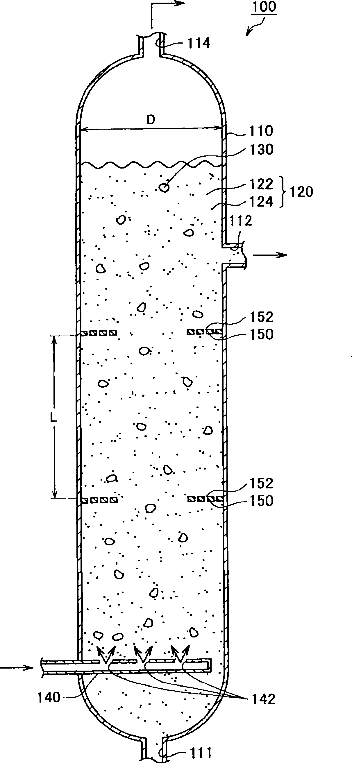
[0056] First, based on figure 1 The configuration of a bubble column type suspension bed FT synthesis reactor 100 (hereinafter simply referred to as "FT reactor 100") as an example of a bubble column type hydrocarbon synthesis reactor according to the first embodiment of the present invention will be described. figure 1 It is a vertical cross-sectional view showing the overall configuration of the FT reactor 100 of this embodiment.
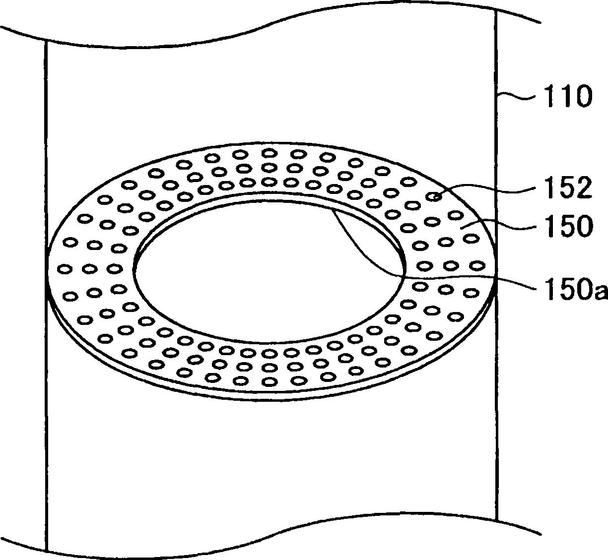
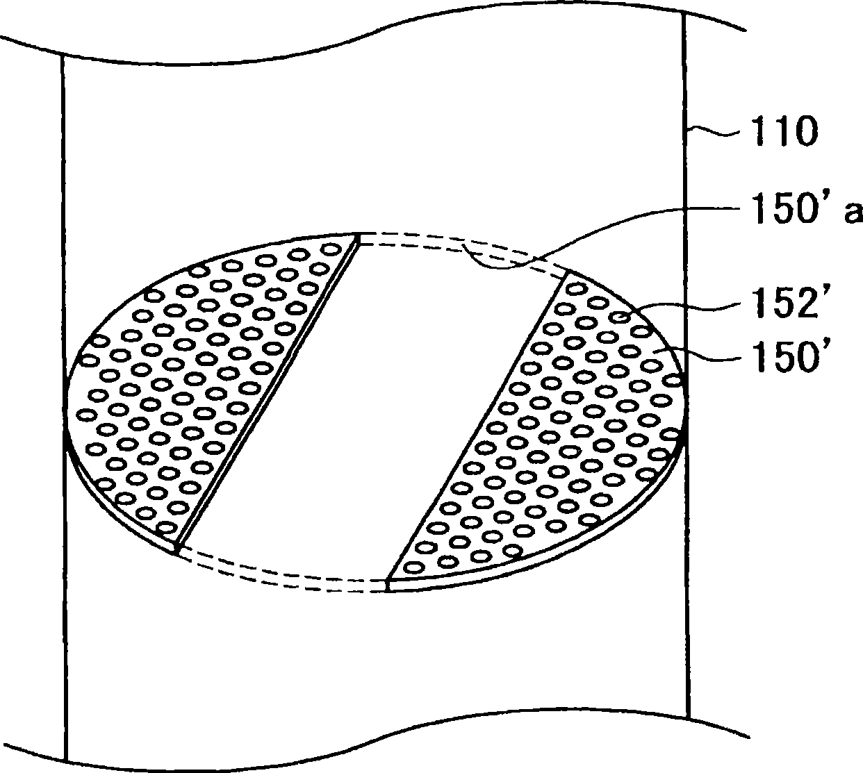
[0057] Such as figure 1 As shown, the FT reactor 100 of this embodiment mainly includes a reactor main body 110, a distributor 140 as an example of a synthesis gas supply unit of the present invention, and a baffle 150 as an example of a baffle member of the present invention.
[0058] The reactor main body 110 is a substantially cylindrical metal vessel with a diameter of about 1 to 20 m, preferably about 2 to 10 m. The height of the reactor main body 10 is about 10 to 50 m, preferably about 15 to 45 m. A slurry 120 in which solid catalyst par...
no. 2 Embodiment approach
[0091] Next, based on Figure 14 The configuration of a bubble column type suspension bed FT synthesis reactor 200 (hereinafter simply referred to as "FT reactor 200") as an example of a bubble column type hydrocarbon synthesis reactor according to the second embodiment of the present invention will be described. also, Figure 14 It is a vertical cross-sectional view showing the overall configuration of the FT reactor 200 of this embodiment.
[0092] Such as Figure 14 As shown, the FT reactor 200 of this embodiment mainly includes: a reactor main body 210, a distributor 240 as an example of a synthesis gas supply part in this embodiment, and a baffle 250 as an example of a baffle member in this embodiment. .
[0093] The slurry 220 is housed in the reactor body 210 . A slurry inlet 211 for introducing a slurry 220 into the reactor body 210 is provided at the bottom of the reactor body 210 . A slurry discharge port 212 for discharging the slurry 220 is provided on the sid...
no. 3 Embodiment approach
[0100] Next, based on Figure 15 The configuration of a bubble column type suspension bed FT synthesis reactor 300 (hereinafter simply referred to as "FT reactor 300") as an example of a bubble column type hydrocarbon synthesis reactor according to a third embodiment of the present invention will be described. also, Figure 15 It is a vertical cross-sectional view showing the overall configuration of the FT reactor 300 of this embodiment.
[0101] Such as Figure 15 As shown, the FT reactor 300 of this embodiment mainly includes: a reactor main body 310, a distributor 340 as an example of a synthesis gas supply part of this embodiment, and a baffle 350 as an example of a baffle member of this embodiment. .
[0102] The slurry 320 is housed in the reactor body 310 . A slurry inlet 311 for introducing slurry 320 into the reactor body 310 is provided at the bottom of the reactor body 310 . A slurry discharge port 312 for discharging the slurry 320 is provided on the side wal...
PUM
| Property | Measurement | Unit |
|---|---|---|
| diameter | aaaaa | aaaaa |
| particle size | aaaaa | aaaaa |
Abstract
Description
Claims
Application Information
 - R&D
- Intellectual Property
- Life Sciences
- Materials
- Tech Scout
- Unparalleled Data Quality
- Higher Quality Content
- 60% Fewer Hallucinations
Browse by: Latest US Patents, China's latest patents, Technical Efficacy Thesaurus, Application Domain, Technology Topic, Popular Technical Reports.
© 2025 PatSnap. All rights reserved.Legal|Privacy policy|Modern Slavery Act Transparency Statement|Sitemap|About US| Contact US: help@patsnap.com