Spinning machine with time-dependent rotational speed control

A speed control and spinning machine technology, which can be used in continuous winding spinning machines, spinning machines, open-end spinning machines, etc., and can solve problems such as large time overhead.

Inactive Publication Date: 2011-08-17
SAURER GERMANY GMBH & CO KG
View PDF0 Cites 0 Cited by
  • Summary
  • Abstract
  • Description
  • Claims
  • Application Information

AI Technical Summary

Problems solved by technology

Changes in the speed of several spinning machines, i.e. reducing and then increasing the speed, require considerable time expenditure

Method used


Image

  • Spinning machine with time-dependent rotational speed control
  • Spinning machine with time-dependent rotational speed control
  • Spinning machine with time-dependent rotational speed control

Examples


Embodiment Construction

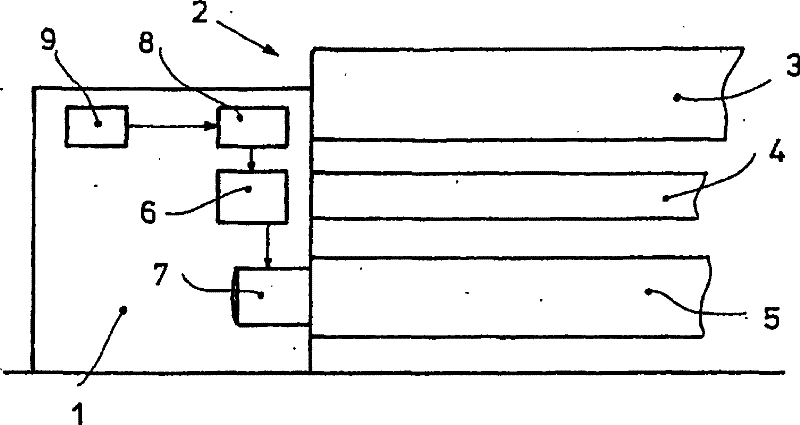
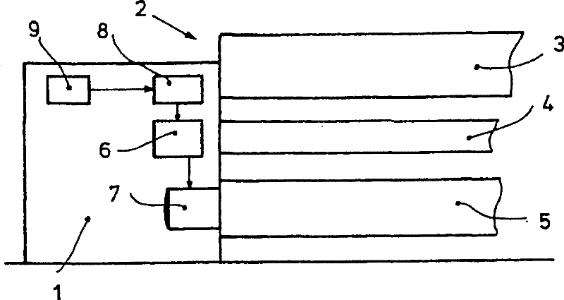
[0015] figure 1 Purely schematically shows, for example, a drive head 1 of a ring spinning machine 2 with a creel 3 , a drafting device 4 and a spindle zone 5 , the ring spinning machine 2 having at least one drive motor 7. The drive motor 7 is supplied by a feed device such as an inverter 6 . Of course, ring spinning machines usually have several motors, which are not shown here.

[0016] The rotational speed of the motor 6 or motors can be determined in a variable manner via the rotational speed supplied to the frequency converter 6 by a rotational speed selector 8 (encoder) arranged in the machine control. With the aid of a manually set speed selector, the motor speed can usually be selected within a wide range as described above.

[0017] According to the invention, the ring spinning machine 2 is equipped with timing means 9 by means of which the rotational speed selector 8 can be set to at least one other rotational speed within a certain period of time.

[0018] The t...


PUM


Abstract

The invention relates to a spinning system comprising a plurality of spinning machines, for example, pre-spinning machines (10) and / or ring spinning machines (11) whose operational speed must be reduced in time slots having reduced service. As a result, a common central time switch (9), which is associated with each machine or one of the machines, impinges upon the rotational speed selector(s) (8) in the control of the machine in order to modify the rotational speed in predefinable time slots.

Description

technical field [0001] The invention relates to a spinning system comprising a plurality of spinning machines, the spinning system having a rotational speed control device which can be influenced automatically. Background technique [0002] Spinning machines are known which are equipped with a longitudinal measuring device, by means of which the rotational speed of the spinning machine can be varied automatically depending on the spinning process. Thus, during the formation of cop bits it can be provided, for example, that the ring spinning machine is set to run at a reduced rotational speed after a package change. When forming the bottom yarn of the bobbin, the yarn balloon is larger and the winding diameter is smaller, and the angle between the yarn tension and the bobbin casing is steep, so the yarn tension is very high. This will lead to a high number of yarn breaks, which should be reduced by reducing the speed of rotation. [0003] In spinning there are time periods ...

Claims


Application Information

Patent Timeline
Patent Type & Authority Patents(China)
IPC IPC(8): D01H1/34
CPCD01H4/42D01H1/34
Inventor 迪特马尔・施特勒海纳・克洛伊伦
Owner SAURER GERMANY GMBH & CO KG
Why Eureka
Try Eureka