
Platform for driving straight line motor of PCB piercing machine

A linear motor and drive platform technology, applied in the direction of electromechanical devices, electric components, electrical components, etc., can solve the problems of small heat dissipation, large thrust, affecting the performance stability and service life of load actuator components, and achieve the implementation effect Good, reduced thrust, reduced overall mass effect

Inactive Publication Date: 2009-05-20
SUZHOU VEGA TECH CO LTD
View PDF0 Cites 17 Cited by
  • Summary
  • Abstract
  • Description
  • Claims
  • Application Information

AI Technical Summary

Problems solved by technology

However, the motion strokes of general industrial applications are limited, and the strokes are generally short; the general mover is composed of copper and steel, and its mass is relatively heavy, which itself consumes more thrust, especially in applications under high acceleration conditions. It consumes a lot of thrust
[0003] Looking further, when the linear motor needs to be driven in the vertical direction, the traditional linear motor installation method must achieve the same motion acceleration as in the horizontal direction, because to overcome gravity, a linear motor with a greater thrust needs to be selected, and the large thrust motor also increases The quality of the moving parts will immediately cause excessive vibration due to the increase in the quality of the moving parts, which will affect the normal operation of the linear motor
[0004] Moreover, since the enameled coil of the mover part will generate heat due to the existence of resistance when it is energized, due to the structure of the existing linear motor drive platform, the heat dissipation volume is too small, and the heat will be transferred to the load part, affecting the load part. Work
At the same time, the load part is often the key executive part. With long-term operation, it will inevitably affect the performance stability and service life of the load executive part, which is not conducive to its application in the field of high-acceleration vertical drive.

Method used


Image

  • Platform for driving straight line motor of PCB piercing machine
  • Platform for driving straight line motor of PCB piercing machine

Examples


Embodiment Construction

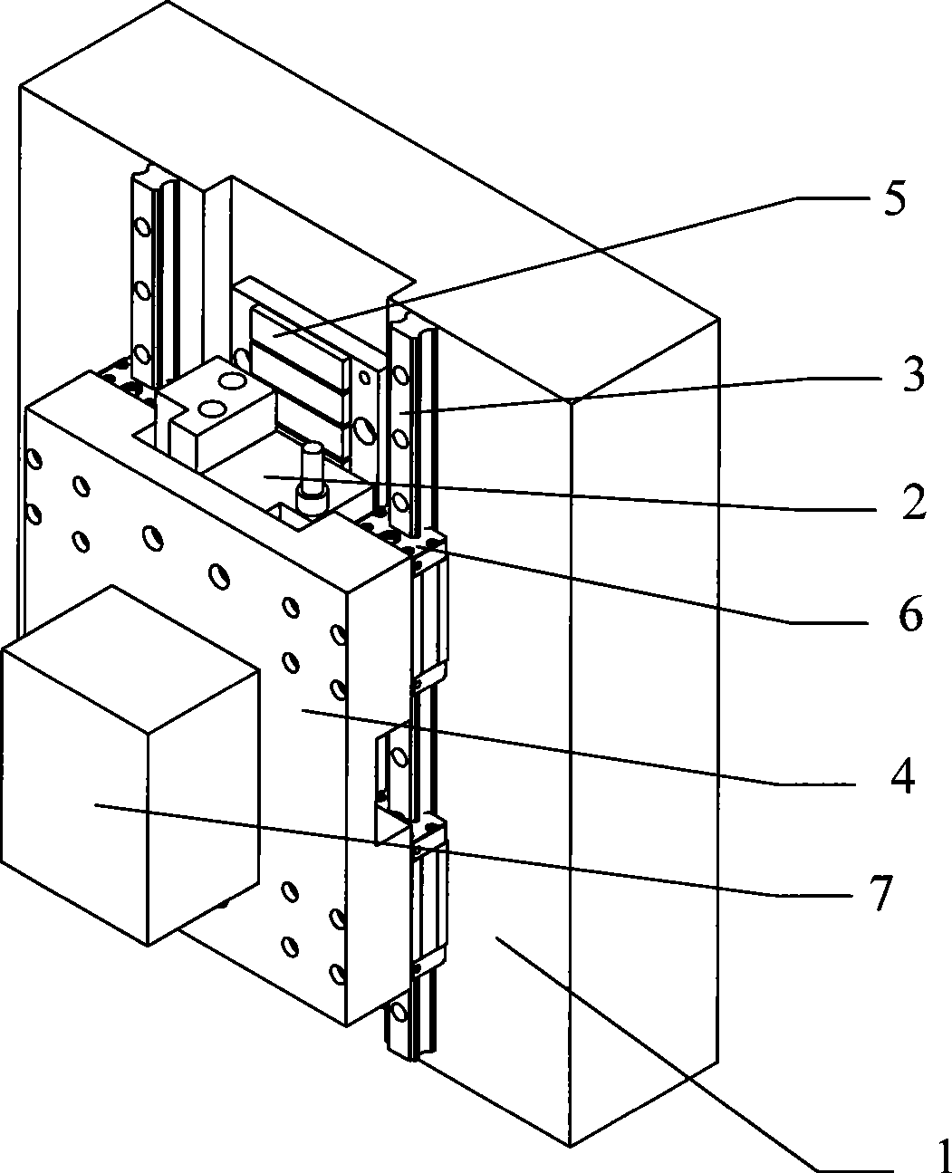
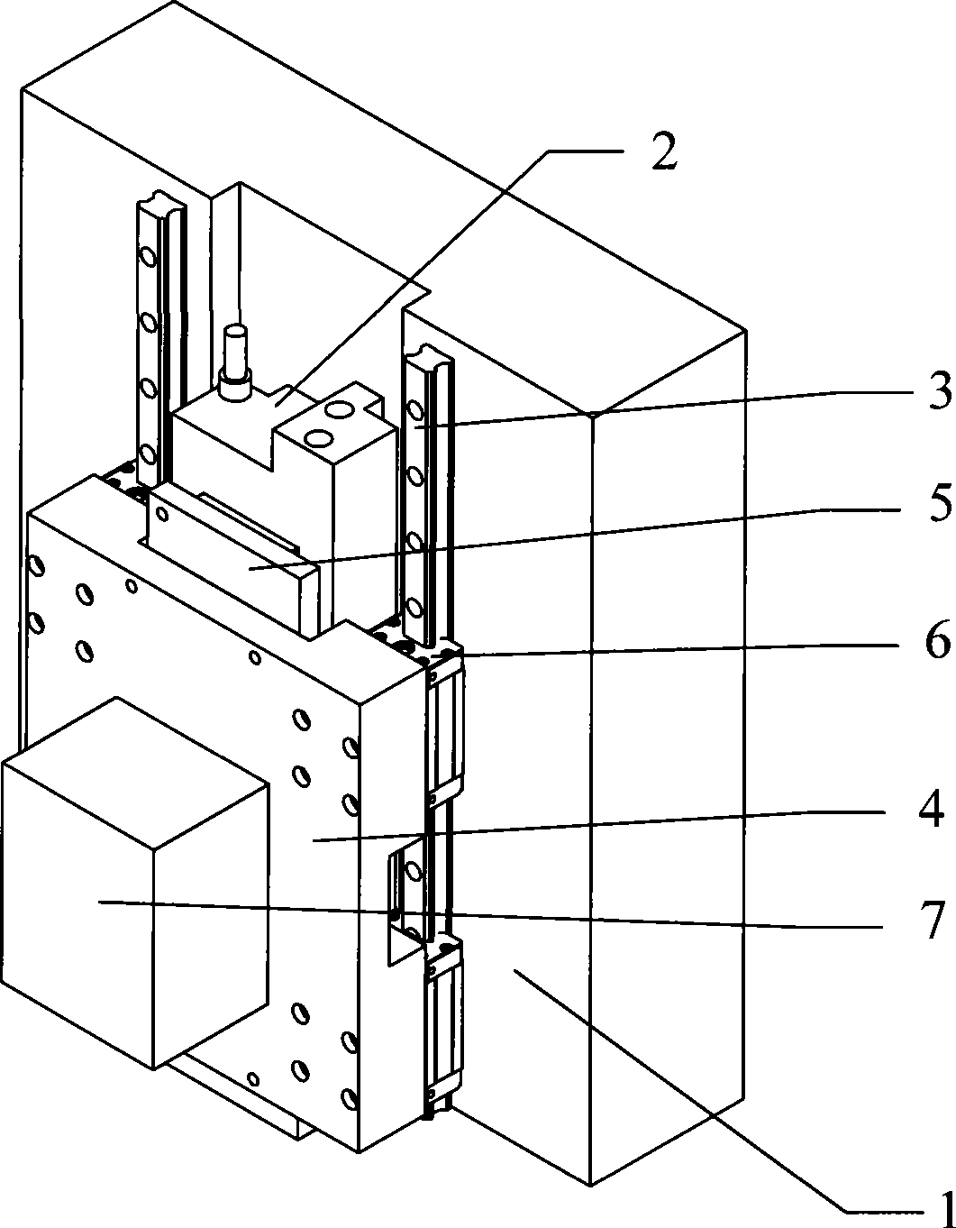
[0020] Such as figure 2 The linear motor drive platform of a PCB drilling machine shown is special in that it includes a base fixed platform 1, a motor mover 2, a guide rail 3, a fixed plate 4, a stator 5, and a slider 6, and the base fixed platform 1 is equipped with motor mover 2 and guide rail 3, the stator 5 is installed on the movable fixed plate 4, the fixed plate 4 is installed on the guide rail slider 6, and the linear motor stator 5 is driven by the electromagnetic thrust of the linear motor and fixed together. The plate 4 moves along the guide rail 3 . That is to say, the motor generates a continuous and constant moving magnetic field thrust after the AC power is connected, and then pushes the fixed plate 4, the stator 5 and the load 7 installed during use to move. At the same time, the base fixed platform 1 is provided with an installation plane on which the linear motor mover 2 is installed, and the guide rails 3 are installed in pairs on both sides of the motor ...


PUM


Abstract

The invention relates to a linear motor drive platform for a PCB driller, which belongs to the technical field of high-speed drive. The platform comprises a fundamental fixed platform, a motor rotor, a guide rail, a fixed plate, a motor stator and a sliding block, wherein the motor rotor and the guide rail are arranged on the fundamental fixed platform; the stator with smaller mass is arranged on the movable fixed plate; the fixed plate is arranged on the sliding block; and the stator moves along the guide rail with the fixed plate. The platform can effectively reduce total mass of moving parts without generating overmuch vibration, and is more effective when the platform drives in vertical direction. Meanwhile, heat generated by the rotor can be consumed in time through the fundamental fixed platform with large volume, so that excellent working environment and stability of the linear motor drive platform can be ensured. Therefore, the platform can be popularized and applied in the same industry.

Description

technical field [0001] The invention relates to a device for improving the effective thrust of a linear motor, in particular to a short-stroke, high-acceleration PCB drilling machine linear motor drive platform applied in a vertical direction, belonging to the technical field of high-speed motor drive. Background technique [0002] As far as the prior art is concerned, common linear motors are divided into two parts: a mover composed of enamelled coils and silicon steel sheets, and a stator composed of industrial pure iron and permanent magnets. Such as figure 1 The current assembly structure shown is to fix the stator and the guide rail on a basic fixed platform, and install the mover on a movable fixed plate installed on the slider of the guide rail. Generate a continuous and constant moving electromagnetic field thrust to push the motor mover and the fixed plate and the load on the fixed plate. In order to adapt to different application fields, the length of the stator ...

Claims


Application Information

Patent Timeline
Patent Type & Authority Applications(China)
IPC IPC(8): B23Q1/26B23Q5/28H02K7/14
Inventor 邱四军
Owner SUZHOU VEGA TECH CO LTD
Learn More