Special fixture for wire plier milling flutes

A special fixture and wire pliers technology, applied in the direction of clamping, milling machine equipment, manufacturing tools, etc., can solve the problems of wasting time, increasing the workload of workers, troublesome processing, etc., to reduce the clamping time, reduce the workload of workers, improve The effect of production efficiency

Inactive Publication Date: 2009-05-20
ZHANGJIAGANG YUCHENG MASCH C0 LTD
View PDF0 Cites 18 Cited by
  • Summary
  • Abstract
  • Description
  • Claims
  • Application Information

AI Technical Summary

Problems solved by technology

[0002] At present, the milling process of the parts of the wire pliers is still in the stage of manual clamping, that is, after the workpiece is placed on the workbench, the workpiece is fixed with a pressure plate and bolts, and due to the uncertainty of the position of the workpiece, each time It is necessary to set the tool during slot milling, which not only wastes time, but also increases the workload of workers, and the processing is more troublesome

Method used


Image

  • Special fixture for wire plier milling flutes
  • Special fixture for wire plier milling flutes
  • Special fixture for wire plier milling flutes

Examples


Embodiment Construction

[0013] The structure and working principle of the special fixture for milling grooves of wire cutters of the present invention will be further described in detail below in conjunction with the accompanying drawings.

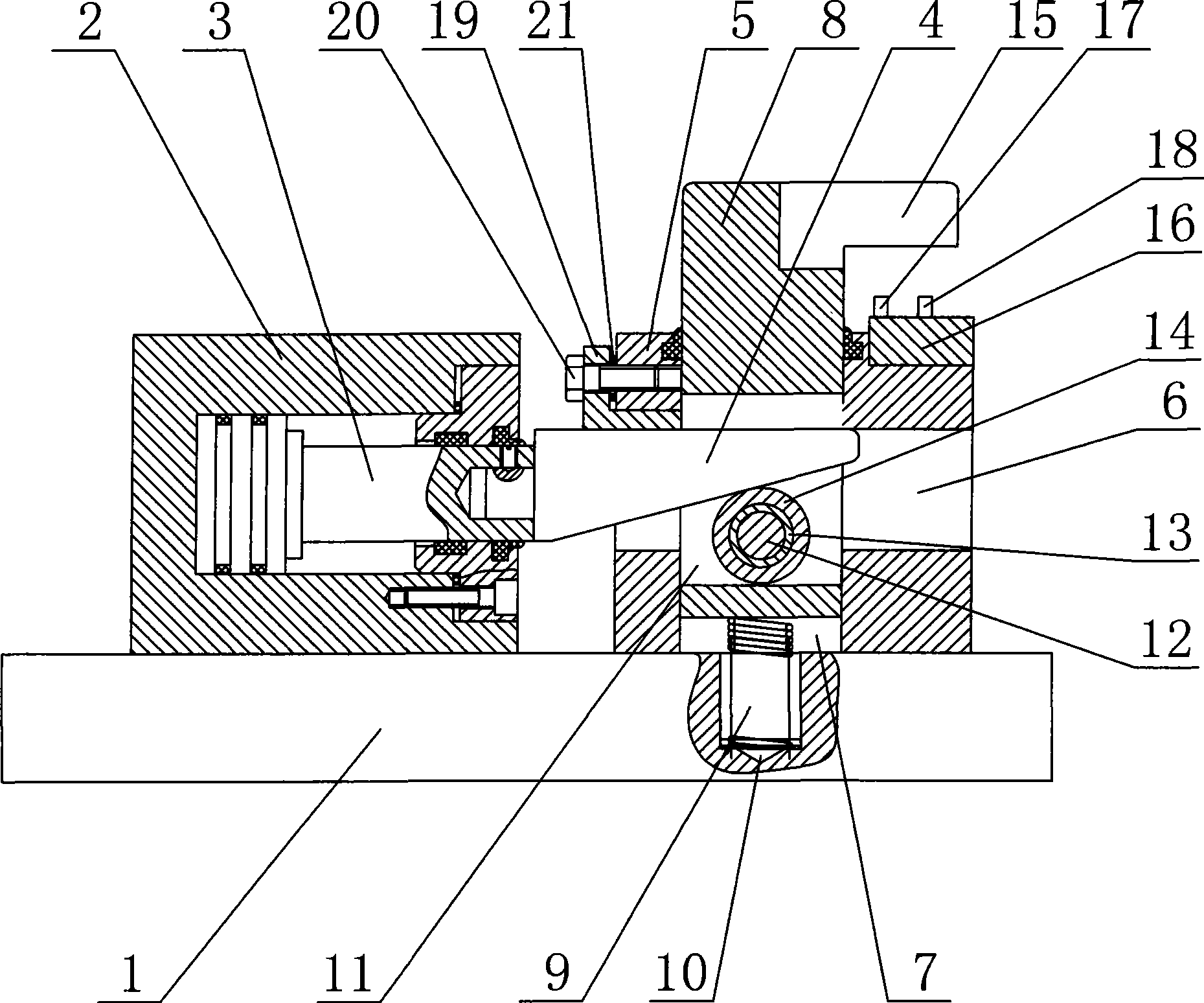
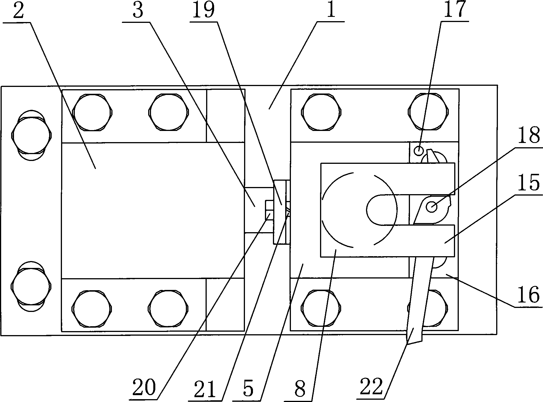
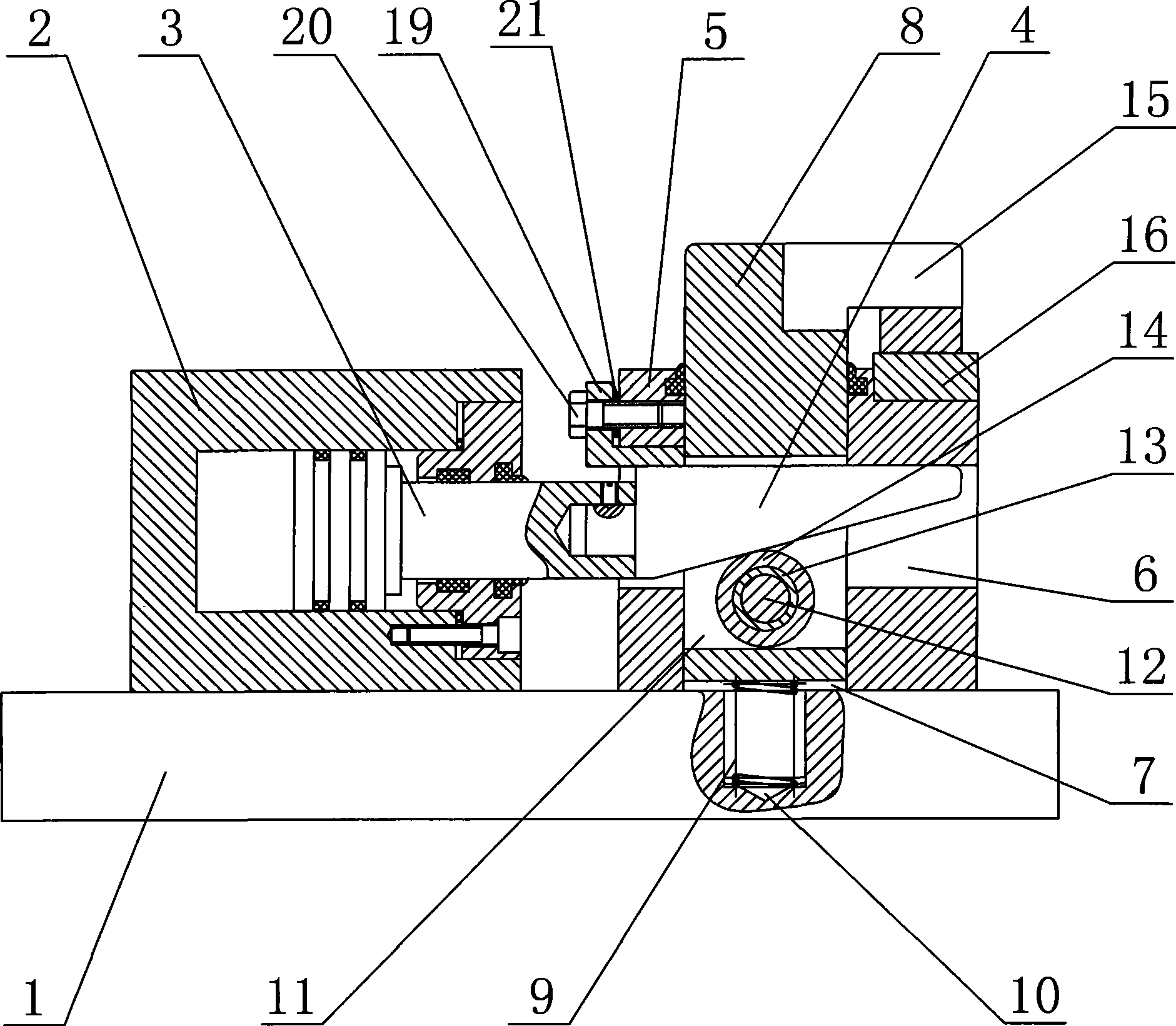
[0014] Such as figure 1 , figure 2 As shown, a special fixture for wire pliers milling slots includes a base plate 1, a hydraulic cylinder 2 is arranged on the base plate 1, a piston 3 is arranged in the cylinder body of the hydraulic cylinder 2, and a wedge 4 is connected to one end of the piston 3. 1 is provided with a fixed seat 5, and a transverse through hole 6 is arranged in the fixed seat 5 along the moving direction of the piston 3, and the wedge 4 can slide in the transverse through hole 6, and the middle part of the fixed seat 5 is also A longitudinal through hole 7 is provided, and a movable pressing block 8 is arranged in the longitudinal through hole 7, and a spring 9 is arranged at the lower end of the movable pressing block 8, and the spring 9 is...


PUM


Abstract

The invention discloses a special clamp for a wire-cutter milling groove capable of quickly clamping a wire-cutter part, which comprises a bottom plate, wherein the bottom plate is provided with a hydraulic cylinder; a wedge block is connected with one end of a piston in the hydraulic cylinder; the bottom plate is provided with a permanent seat; the inside of the permanent seat is provided with a transverse through hole along the motion direction of the piston; the wedge block can slide in the transverse through hole; the middle of the permanent seat is also provided with a vertical through hole; a movable briquette is arranged in the vertical through hole; a spring is arranged on the lower end of the movable briquette; the inside of the movable briquette is provided with a through hole; the wedge block passes through the through hole; a shaft is arranged in the through hole; a roller wheel is sleeved on the shaft; the circumference of the roller wheel is contacted with the lower bevel edge of the wedge block; a bump is arranged on the upper lateral part of the movable briquette; and a jaw block is arranged under the bump, is fixed on the permanent seat, and is provided with a retainer ring and a pin. The special clamp is suitable for clamping the wire-cutter part so as to carry milling groove processing on the part.

Description

technical field [0001] The invention relates to a special clamp for wire pliers slot milling used for slot milling processing of wire pliers parts. Background technique [0002] At present, the milling process of the parts of the wire pliers is still in the stage of manual clamping, that is, after the workpiece is placed on the workbench, the workpiece is fixed with a pressure plate and bolts, and due to the uncertainty of the position of the workpiece, each time It is necessary to set the tool during slot milling, which not only wastes time, but also increases the workload of workers, and the processing is troublesome. Contents of the invention [0003] The technical problem to be solved by the invention is to provide a special clamp for wire cutter slot milling that can quickly clamp parts of the wire cutter. [0004] In order to solve the above problems, the technical solution adopted by the present invention is: a special fixture for wire cutter milling slots, includi...

Claims


Application Information

Patent Timeline
Patent Type & Authority Applications(China)
IPC IPC(8): B23Q3/06B23C3/28
Inventor 夏小帅
Owner ZHANGJIAGANG YUCHENG MASCH C0 LTD
Why Eureka
Try Eureka