Impedance matching methods and systems performing the same

An impedance matching and matching device technology, applied in impedance networks, AC network circuits, electrical components, etc., to solve problems such as wandering, inability to completely remove reflected waves, and matching delays

Active Publication Date: 2009-05-20
PLASMART
View PDF9 Cites 8 Cited by
  • Summary
  • Abstract
  • Description
  • Claims
  • Application Information

AI Technical Summary

Problems solved by technology

[0008] However, the conventional approach produces several technical limitations as follows: (1) convergence failure of the matching state due to strong dependence on the initial state; (2) matching delay due to instability near the matchin

Method used


Image

  • Impedance matching methods and systems performing the same
  • Impedance matching methods and systems performing the same
  • Impedance matching methods and systems performing the same

Examples


Embodiment Construction

[0068] The invention relates to a matching method of a pulse mode and a continuous wave (CW) mode. The pulse mode matching method can be combined with all conventional continuous wave (CW) mode matching methods. Also, the new CW mode matching method described below can be combined with the pulse mode matching method.

[0069] When the RF power supply is operating in pulsed mode, the matching system operates differently during the on-time interval when the RF power supply is on than the off-time interval when the RF power supply is off. Specifically, the pulse mode can be divided into a slow pulse mode and a fast pulse mode for matching.

[0070] That is, in the case of slow pulse mode (eg, below about 500 Hz), the value of the variable device in the matching network only changes during the on-time interval of the RF power supply, but not during the off-time interval of the RF power supply. Thus, fast matching is achieved since the values ​​of the variable devices in the matc...


PUM


Abstract

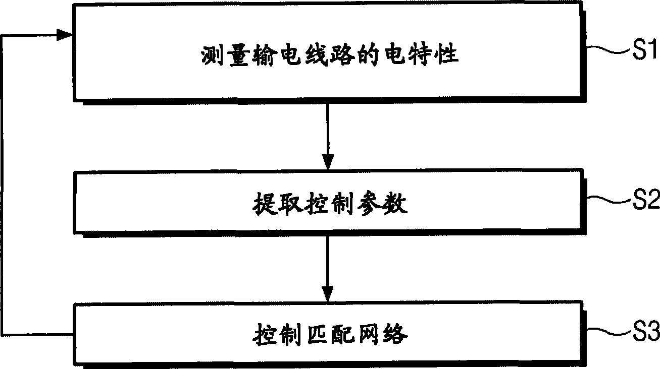
Provided are an impedance matching method and a matching system performing the same. The method includes: measuring an electrical characteristic of the power transmission line; determining a pulse mode of the power source; extracting a control parameter for impedance matching from the electrical characteristic of the power transmission line; and controlling the matching system through the controlparameter, wherein the matching system is controlled differently according to the pulse mode.

Description

[0001] Cross References to Related Applications [0002] This application claims priority from Korean Patent Application No. 10-2007-0116023 filed on November 14, 2007, the entire contents of which are hereby incorporated by reference. technical field [0003] The invention disclosed herein relates to impedance matching, and more particularly, to an impedance matching method used in electrical systems such as plasma systems, nuclear magnetic resonance systems, communication systems, and power transmission lines, and a method for implementing the impedance matching method system. Background technique [0004] If there is an impedance mismatch between the source and the load, the power delivered to the load will not be maximized and precise power control will not be possible. Therefore, electrical systems such as plasma systems, nuclear magnetic resonance systems, communication systems, high-frequency induction heating devices, and power transmission lines include impedance m...

Claims


Application Information

Patent Timeline
IPC IPC(8): H03H7/40H02J3/00
CPCH03H7/40H05H1/24
Inventor 金宰显李相元李容官
Owner PLASMART
Why Eureka
Try Eureka