Sample imaging device

a sample imaging and sample technology, applied in the field of sample imaging devices, can solve the problems of unnecessarily complex and uneconomical devices, difficult to service, and inability to use such powerful lamps with which to measure, etc., and achieve the effects of short measuring time, high throughput screening, and high accuracy

Inactive Publication Date: 2002-04-23
WALLAC
View PDF3 Cites 34 Cited by
  • Summary
  • Abstract
  • Description
  • Claims
  • Application Information

AI Technical Summary

Benefits of technology

ADVANTAGES OF THE DEVICE RELATING TO THE INVENTION
The present imaging device provides a solution to the problem of how to realize a sufficiently powerful lamp unit which produces a sufficiently short light pulse. This type of unit comprising several flash lamps is the only possible lamp for many time-resolved fluorescence measurements. One example of these is homogeneous fluorescence assay LANCE, which is a trademark of Wallac Oy. No such powerful lamp is known with which measurement can take place within a sufficiently short measuring time. The measuring time should be short, e.g. 2 minutes, in order for the total measuring time in High Throughput Screening to be acceptable. The total number of samples in one HTS run may be, for example, 100 000 samples, that is, sample wells. Measuring such a large number of sample wells by traditional fluorometric means would take an extremely long time. The amount of hazardous waste produced would also be considerably higher. A combination of a powerful pulsed laser and a dye laser could in principle be used, but it is an unnecessarily complex and uneconomical device which is also difficult to service.
The intervals for changing the lamp bulbs of the light source become extremely long when a lamp combination consisting of flash lamps is used. This is of considerable importance in HTS runs where the aim is to minimize the number of stoppages. When using conventional continuous, that is, continuous wave lamp units, for example, mercury or xenon arc lamps or halogen lamps, the lamp changing intervals are without exception too short considering the demands of HTS screening. One of the few possible solutions when using continuous lamps would be that the lamp could be changed automatically, but it is rather difficult to arrange this to function reliably.
The device relating to the invention combines the absorption measurements of both the near ultraviolet region and of visible light, or, vice versa, transmittance measurements, that is, in practice photometric measurements: the absorption of near UV is required especially in the applicant's LANCE measurements. Absorption measurements in the visible region are in the nature of standards in terms of measuring technique.
The difficulties in using both absorption modes, such as near UV and visible region light mainly concern optics. It is almost impossible, or extremely uneconomical, to construct a telecentric lens with such a high light-collecting efficiency that would transmit effectively the wavelengths of both near UV and visible region light. Typically, a lens system which collects light efficiently and has good resolution can be made either in the near UV region, or alternatively in the wavelengths of visible light. This means that typically only absorption imaging in the visible region or absorption in the near UV light region are possible. In the application relating to the invention, on the other hand, a special scattering plate is used by means of which both near UV and visible light absorption measurements can be imaged.
The light source solution relating to the invention is advantageous for measuring numerous samples done by imaging, for example, especially in demanding applications such as HTS screening and both time-resolved and prompt fluorescence measurements. The device is able to image absorption measurements efficiently both in the near UV light region, that is, in 300-400 nm, and in the visible region, that is, 400-800 nm.

Problems solved by technology

No such powerful lamp is known with which measurement can take place within a sufficiently short measuring time.
Measuring such a large number of sample wells by traditional fluorometric means would take an extremely long time.
A combination of a powerful pulsed laser and a dye laser could in principle be used, but it is an unnecessarily complex and uneconomical device which is also difficult to service.
One of the few possible solutions when using continuous lamps would be that the lamp could be changed automatically, but it is rather difficult to arrange this to function reliably.
The difficulties in using both absorption modes, such as near UV and visible region light mainly concern optics.
It is almost impossible, or extremely uneconomical, to construct a telecentric lens with such a high light-collecting efficiency that would transmit effectively the wavelengths of both near UV and visible region light.
1. High average total pulse power
2. Narrow pulse width, which is required in the embodiment used as an example
3. The use of several lamps makes it possible to select the pulse energy of a single lamp so that the fluorescent sample will not become saturated. If a single lamp with high pulse power were used, the sample might become saturated, which would mean a sharp drop in the sensitivity of detection.
4. The use of several lamps also means that even if there should occur a fault in a single lamp, the overall efficiency remains almost unchanged in proportion to the number of lamps.
5. Using several pulse mode lamps also means that the intervals for changing the lamps are extremely long, for example, about six months. This is due to the fact that a pulse mode lamp is switched on only when it is really used. There is no wastage.
It is not worthwhile, nor possible, to switch a continuous lamp off for example for a 15 minute waiting period, because the lamp reignites slowly due to the increase in the internal gas pressure inside the lamp, which is due to the warming up of the lamp following its use, this making it difficult, or even impossible, to reignite the lamp .
In addition, stabilizing the arc lamp, that is, stabilizing its power within a desired wavelength region cannot be performed successfully if the lamp is switched on and off, for example, at 15 minute intervals.
However, the light pulse has a "tail" extending up to about 50 microseconds, the said tail limiting the sensitivity of measurements when the aim is to achieve extreme sensitivity.
It is not worth using the rotating mirror system if continuous light sources are used as lamps.

Method used


Image

  • Sample imaging device
  • Sample imaging device
  • Sample imaging device

Examples


example 1

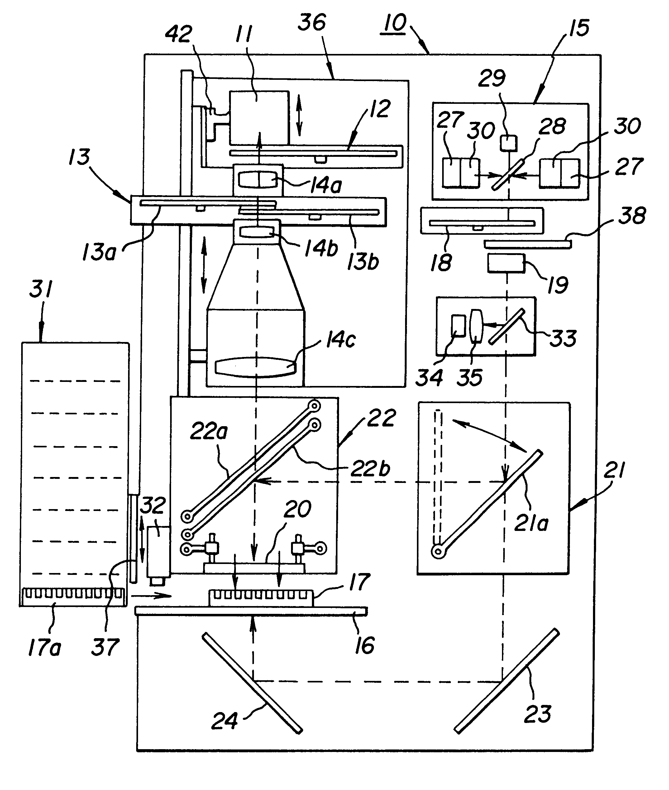
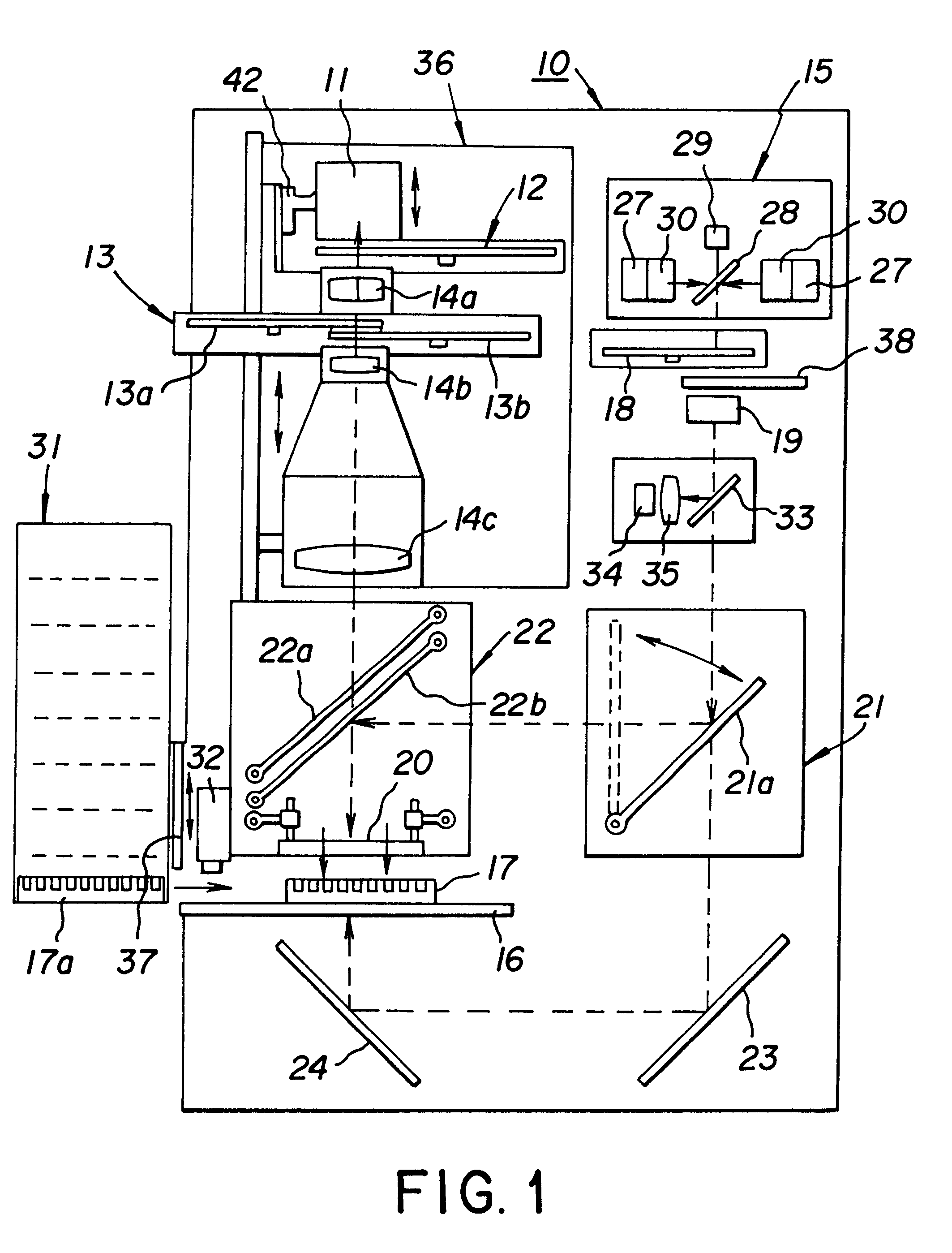
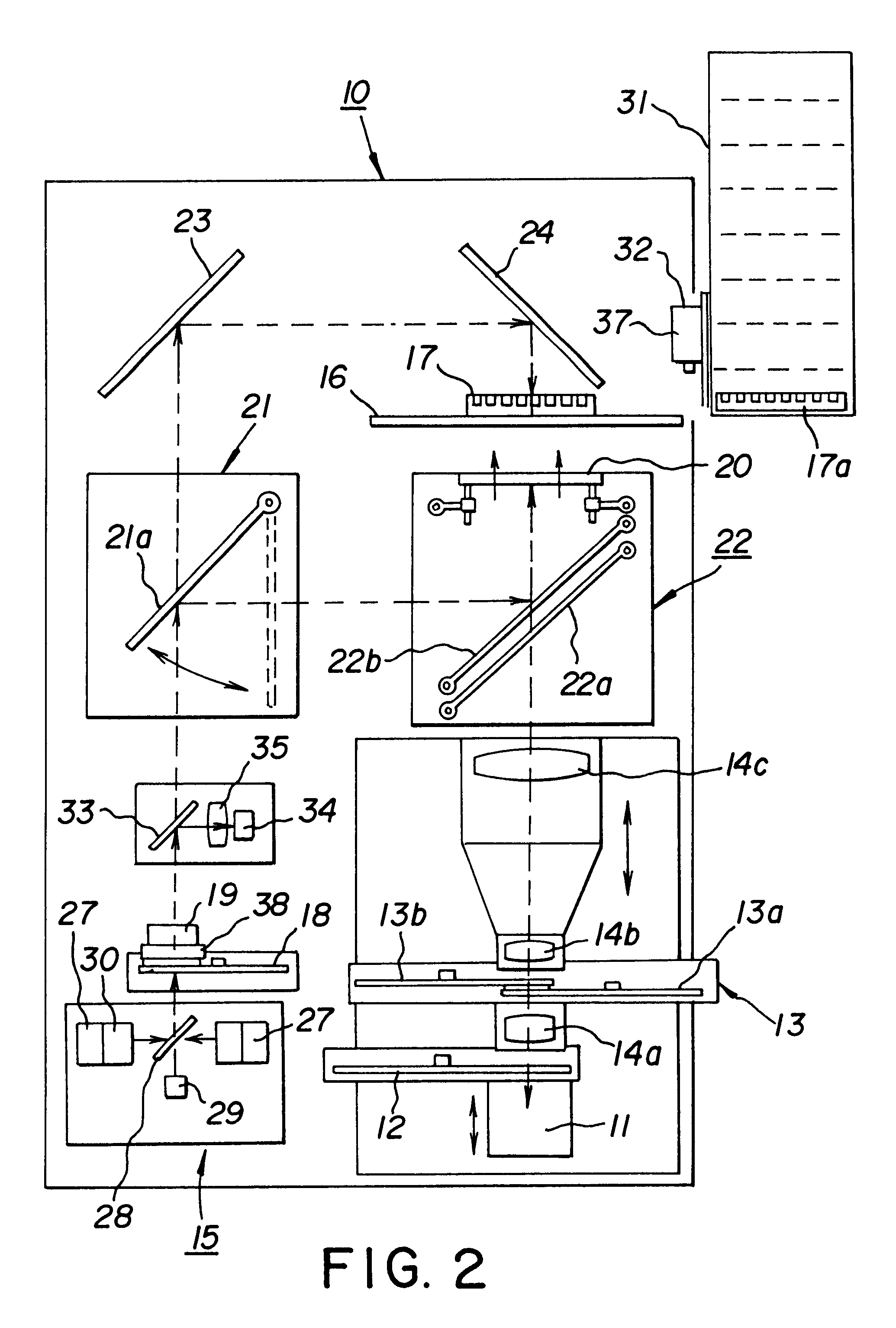
The light source 15 of the example of an embodiment shown in FIG. 5 comprises four flash lamps, where the rotational frequency of the rotating mirror is 200 Hz. This means that the interval between two successive pulses of one lamp is 5 ms. According to the invention, the lamps are controlled so that they flash at a 1.25 ms time difference with respect to each other, which means that during one 5 ms period, a total of four flashes of light are obtained. The combined pulse frequency of the lamps achieved with the construction described in the example is in this case 800 Hz. This is four times greater compared with that obtained with a single lamp. By means of this solution the optical power of the light source 15 is quadrupled compared with the optical power obtained with one lamp. When even greater optical power is required, the number of flash lamps can be further increased, for example, to eight flash lamps.

example 2

In the example of an embodiment shown in FIGS. 3 and 4, the speed of rotation of the chopper 13 discs 13a and 13b is 24000 rpm, that is, the rotational frequency is 400 Hz, in other words the wheel rotates at 400 rpm. If the light chopper disc has two apertures 26, it will open 48000 times per minute, that is, 800 times per second. The opening frequency of the apertures is in that case 800 Hz.

Since one flash of light emitted by the flash lamp should correspond to each aperture of the light chopper, the total frequency of the pulse light source should also be 800 Hz. This means that in the example of the embodiment shown in FIGS. 4 and 5, it is advantageous to modify the light source so that it incorporates eight flash lamps flashing at 1.25 ms intervals. The frequency of each individual lamp is 100 Hz, that is, an individual lamp flashes 100 times per second. This means that the rotational frequency of the rotating mirror should be 100 Hz, or 6000 rpm. During one rotation of the mir...

example 3

Four apertures in the chopper discs, speed of rotation of chopper discs 24000 rpm, flashing interval 1.25 ms / 2=0.625 ms, eight lamps in the light source, speed of rotation of rotating mirror 12000 rpm.


PUM

PropertyMeasurementUnit
poweraaaaaaaaaa
wavelengthaaaaaaaaaa
thicknessesaaaaaaaaaa

Abstract

An imaging device for biochemical or medical samples, the pulse mode light source of which incorporates flash lamps and a rotating mirror in an inclined position, the said mirror reflecting the light emitted by each flash lamp in turn along the same optical path to the sample. The flash lamps are switched on alternately in phases and synchronised with the rotating mirror and the emission light chopper, which comprises two rotating discs. The turning mirror directs the light at the sample from above and/or below, in which case a double-acting transparent scattering plate can be used.

Description

OBJECT OF THE INVENTIONThe object of the present invention is a system for measuring biochemical and medical samples, the said measuring being carried out by imaging. The objects of imaging are mainly regular macro-size sample matrices, gels, Petri dishes or completely free-form samples, such as, for example, biological sections. The signal to be imaged is ultraviolet light, visible region light, or infrared light.Light-producing mechanisms are:1) luminescence, such as chemiluminescence and bioluminescence, in which case the light p produced by each sample at different points of the sample is measured,2) fluorescence, in which case the amount of emission light produced by special excitation light at different points of the sample is measured ed, and in addition3) the amount of reflection, scattering, or absorption at different points of the sample, resulting from the illumination of the sample.PRIOR ARTIn known measuring devices many different types of sample plates are used, in whi...

Claims


Application Information

Patent Timeline
Patent Type & Authority Patents(United States)
IPC IPC(8): G01N21/25G01J3/08G01J3/10
CPCG01J3/08G01N21/253G01J3/10G01J3/021G01J3/0232G01N2201/0625G01N2201/06146
Inventor VAISALA, MIKKONURMI, JARMOKORPI, JARMOHARJU, RAIMO
Owner WALLAC
Why Eureka
Try Eureka