Vertical cavity surface emitting laser (VCSEL) arrays pumped solid-state lasers

a laser array and laser technology, applied in the field of solid-state lasers, can solve the problems of high trigger voltage, low coupling efficiency, and serious limitations of all pumping sources, and achieve the effects of efficient coupling, compact structure, and high efficiency over wide temperature and performance ranges

Active Publication Date: 2008-09-30
PAVILION INTEGRATION
View PDF19 Cites 36 Cited by
  • Summary
  • Abstract
  • Description
  • Claims
  • Application Information

AI Technical Summary

Benefits of technology

[0014]Accordingly, we have invented a solid-state laser that is pumped by VCSEL arrays. Our invention provides for efficient coupling and absorption of the partially coherent monochromatic pump light, resulting in a compact, robust, and relatively low-cost laser that may efficiently operate over wide temperature and performance ranges while consuming relatively low energy.
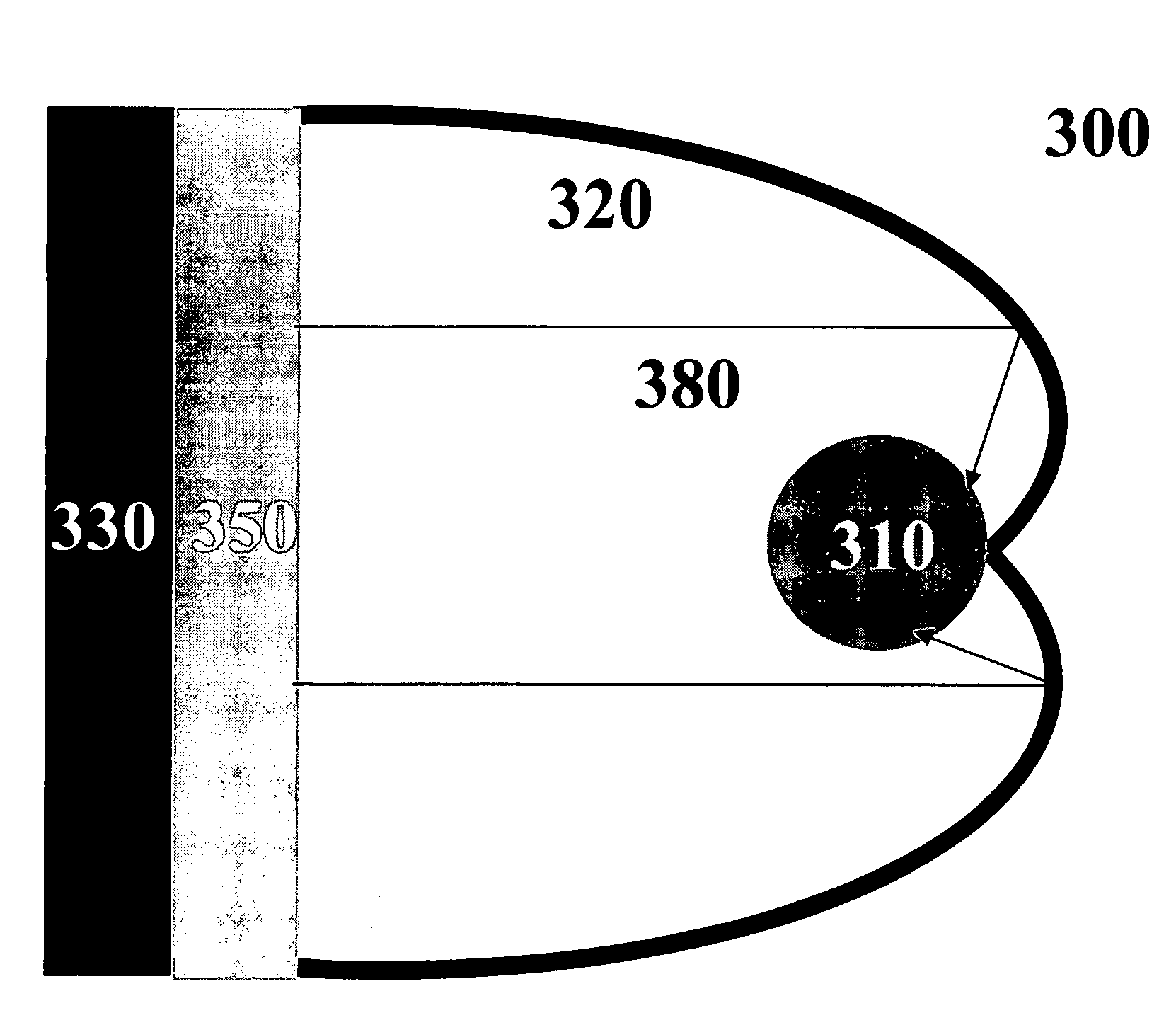
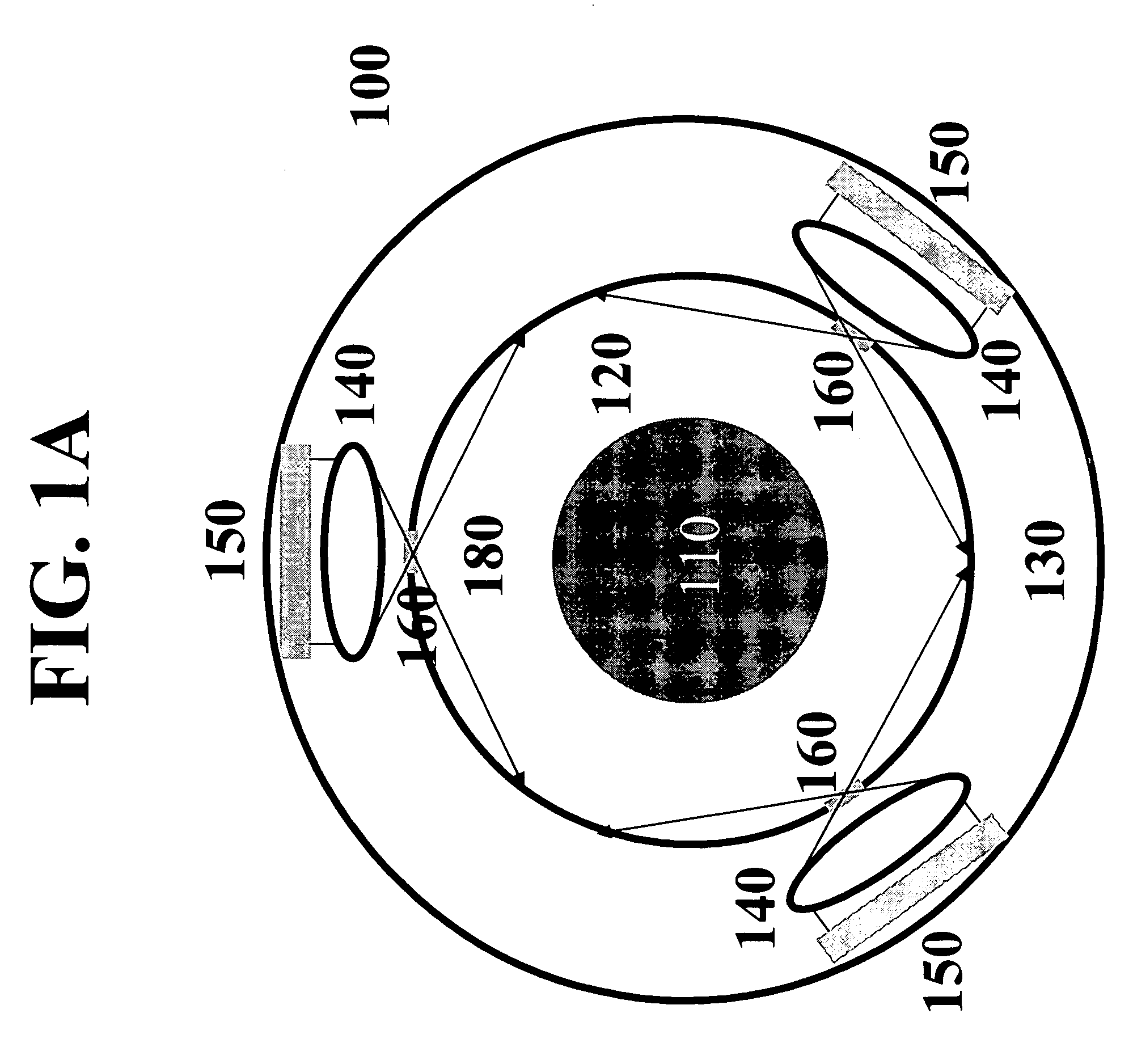
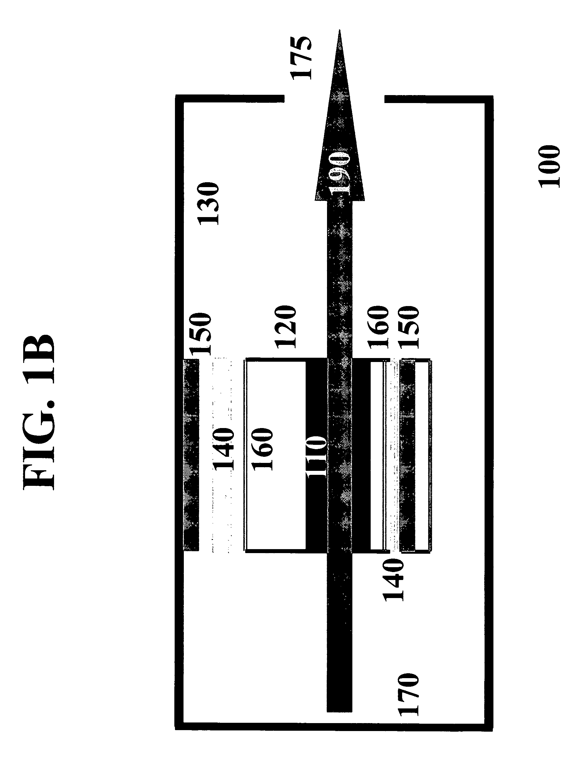
[0015]Viewed from a first aspect and according to our invention, pump light emanating from a partially coherent monochromatic light source such as a VCSEL array is coupled into a laser gain medium through the use of a diffusing pump chamber. Our inventive diffusing pump chamber provides for multi-bounce reflections of unabsorbed pump light, resulting in uniform distribution of gain medium excitation. One preferred embodiment of our inventive diffusing pump chamber is a hollow cylinder coaxially surrounding the gain medium. There are one or more windows for transmission of the pump light. One or more VCSEL arrays are disposed outside the diffusing pump chamber with even separation along the perimeter. Another preferred embodiment of our inventive diffusing pump chamber is a highly reflecting Compound Parabolic Concentrator (CPC). A 2-D VCSEL array is employed as the pump source and the gain medium is located at the focusing point of the diffusing pump chamber. Our inventive structure provides a convenient mechanical mounting for the pump source and associated driver electronics. Still further, our inventive structure provides for the efficient dissipation of heat, resulting in a laser capable of sustained, high-power, continuous (CW) or pulsed output—including those with extremely high repetition rates.
[0016]Viewed from a second aspect, our inventive teachings result in solid-state lasers exhibiting three basic characteristics, namely, 1) the efficient delivery of pump energy into a lasing media; 2) the efficient transfer of excited energy into stimulated emission with minimum loss from spontaneous emission or non-radiative quenching—a characteristic particularly important for laser materials having short upper state lifetimes; and 3) the novel integration of technologies such as high efficiency and high power VCSEL arrays and solid-state laser materials in conjunction with the uniform absorption of pumping energies. The resulting inventive structures are highly flexible, and therefore applicable to a large group of lasing media, operating in different modes that may be applied to a plethora of laser systems at wavelengths that have important applications not available to direct pumping technologies.
[0017]Viewed from a third aspect, our inventive teachings may be incorporated with other technologies such as wavelength conversion and / or Q-switch for various applications. According to our invention, a nonlinear optical crystal may be introduced in the laser path for intracavity Optical Parametric Oscillation (OPO) or Second-Harmonic Generation (SHG). Moreover, a birefringent crystal may be sandwiched in between the gain medium and the nonlinear optical crystal for polarization / wavelength selection and / or elimination of possible interference between the signal and the idler in a singly resonant OPO. These crystals are optically bounded to form a monolithic or hybrid structure. High power laser output at a desired wavelength is achievable through continuously pumped, repetitively Q-switched operation.

Problems solved by technology

All of these pumping sources have serious limitations and drawbacks, however.
However, due to their non-monochromatic output, the coupling efficiency is generally low.
Increasing the flash-lamp's filling pressure could improve the conversion efficiency, however, this would require higher trigger voltage and the simmer current would be more difficult to establish and maintain.
The flash-lamp's low coupling efficiency causes a large amount of heat to be generated during the pumping, which limits repetition rates of solid-state lasers pumped by flash lamps.
Additionally, the excessive heating leads to undesirable thermal effects such as thermal birefringence, thermal lensing, and even thermal damage.
Finally, flash lamps typically exhibit short operating lifetimes, causing frequent replacement necessary.
Unfortunately however, semiconductor lasers are effectively low-peak-power devices and as such, are not best applicable to high-peak-power pulsed mode operations and can be easily damaged by electrostatic discharge or current spikes.
In addition, diode laser pumping often does not operate over desirable temperature ranges unless inefficient and oftentimes cumbersome temperature control is used.
Moreover, diode lasers have a relatively short lifetime of only 5,000 to 10,000 hours and their cost is high.
Side-pumped lasers typically use cylindrical rods and thus do not exhibit efficient mode-pump overlap, which is particularly problematic for high power scaling.
In addition, low dopant percentage has to be used to avoid absorption of pumping energy concentrated near the surface of the laser medium, which may lead to poor overlap between the laser mode and the pumped volume, as well as degradation of the quality of the laser beam due to hot spots inside the gain medium.

Method used


Image

  • Vertical cavity surface emitting laser (VCSEL) arrays pumped solid-state lasers
  • Vertical cavity surface emitting laser (VCSEL) arrays pumped solid-state lasers
  • Vertical cavity surface emitting laser (VCSEL) arrays pumped solid-state lasers

Examples


example one

[0062]The gain medium 810 is Nd:YAG, which is pumped by an odd number of VCSEL arrays at 808 nm to produce laser emission at 1064 nm. High-power green light at 532 nm is produced after SHG in the nonlinear optical crystal 820.

example two

[0063]The gain medium 810 is Nd:YVO4, which is pumped by an odd number of VCSEL arrays at 808 nm to produce laser emission at 1064 nm. High-power green light at 532 nm is produced after SHG in the nonlinear optical crystal 820. The birefringent crystal 830 is removed in this configuration.

example three

[0064]The gain medium 810 is Nd:YAG, which is pumped by an odd number of VCSEL arrays at 808 nm to produce laser emission at 1064 nm. The birefringent crystal 830 supports the laser oscillation polarized normal to its principal plane and suppresses another component. Intracavity OPO is singly resonated at the signal wavelength. Resonant oscillation at the idler wavelength is suppressed by the walk-off effect in 830. Cr:YAG is utilized as passive Q-switch element 840. Q-switched eye-safe laser output at 1.54 μm is produced after OPO in KTP crystal 820.


PUM


Abstract

Solid-state lasers pumped by incoherent or partially coherent, monochromatic light sources such as high power VCSEL arrays. Efficient and uniform injection of pumping energy into gain medium is achieved through spectral match of the pump source with the gain medium absorption and multi-bounce reflections of unabsorbed pump light in a diffusing pump chamber. One preferred embodiment of the diffusing pump chamber is a hollow cylinder coaxially surrounding the gain medium. One or more transparent windows, slit-shaped or otherwise, for transmission of pump light are evenly distributed around the perimeter of the chamber and are parallel to the axis. Another preferred embodiment of the diffusing pump chamber is a highly reflecting compound parabolic concentrator. A 2-D VCSEL array is employed as the pump source and the gain medium is located at the focusing point of the chamber. This invention demonstrates solid-state lasers that are compact, robust, low-cost, and able to produce high power output in CW or pulse modes for practical applications. An important application of the present invention is high-power solid-state lasers featuring wavelength conversion such as optical parametric oscillation and second-harmonic generation. Another important application of the present invention is injection seeding, especially for pulse mode with high repetition rates.

Description

CROSS REFERENCE TO RELATED APPLICATION[0001]This application claims the benefit of U.S. Provisional Application No. 60 / 676,619, filed Apr. 29, 2005, which is hereby incorporated by reference in its entirety.FIELD OF THE INVENTION[0002]This invention relates generally to the field of solid-state lasers, and more particularly, it relates to solid-state lasers pumped by incoherent or partially coherent, monochromatic light sources such as vertical cavity surface emitting laser (VCSEL) array or arrays.BACKGROUND OF THE INVENTION[0003]Solid-state lasers have found applications in all areas where high peak power or high continuous power are required. Examples include material processing (cutting, drilling, welding, marking, heat treating, etc), semiconductor fabrication (wafer cutting, IC trimming), graphic arts (printing, copying), test equipment (confocal microscope), biotechnology instrumentations (proteomics, DNA sequencing, tomography, flow cytometry), medical applications (diagnosis...

Claims


Application Information

Patent Timeline
Patent Type & Authority Patents(United States)
IPC IPC(8): H01S3/091
CPCH01S3/025H01S3/0941H01S3/08054H01S3/094084H01S3/1083H01S3/1673H01S3/1312H01S3/161H01S3/1611H01S3/1618H01S3/1653H01S3/109
Inventor LUO, NINGYIZHU, SHENG-BAI
Owner PAVILION INTEGRATION
Why Eureka
Try Eureka