Device for melt spinning, treating and winding synthetic threads

A texturing machine and crimping technology, applied in the direction of stretch spinning, textile and paper making, conveying filamentous materials, etc., to achieve high practical effect

Inactive Publication Date: 2009-05-20
OERLIKON TEXTILE GMBH & CO KG
View PDF5 Cites 21 Cited by
  • Summary
  • Abstract
  • Description
  • Claims
  • Application Information

AI Technical Summary

Problems solved by technology

However, the handling unit arranged between the winding unit and the spinning unit is intended to guide multiple filaments, so individual guidance of the filaments in the spinning station is not possible

Method used


Image

  • Device for melt spinning, treating and winding synthetic threads
  • Device for melt spinning, treating and winding synthetic threads
  • Device for melt spinning, treating and winding synthetic threads

Examples


Embodiment Construction

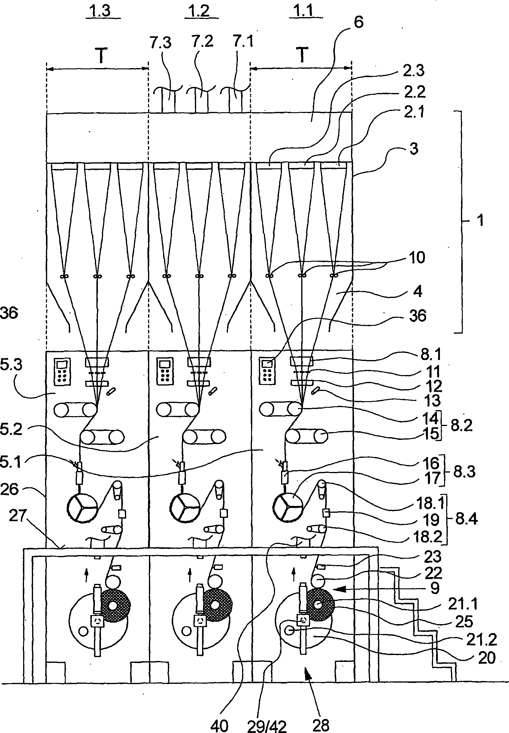
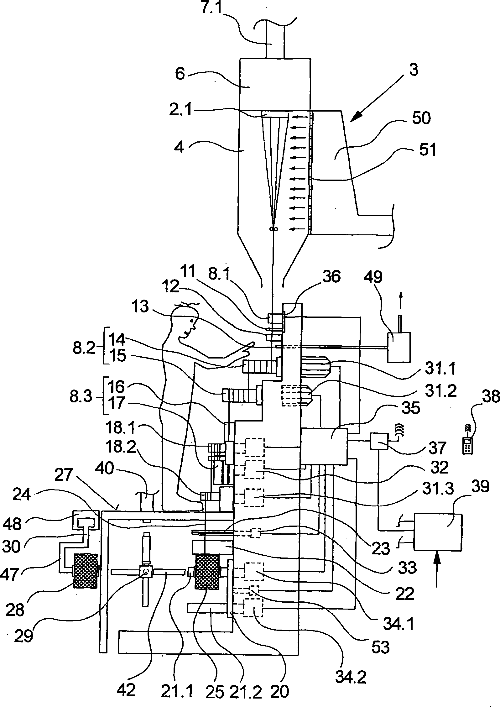
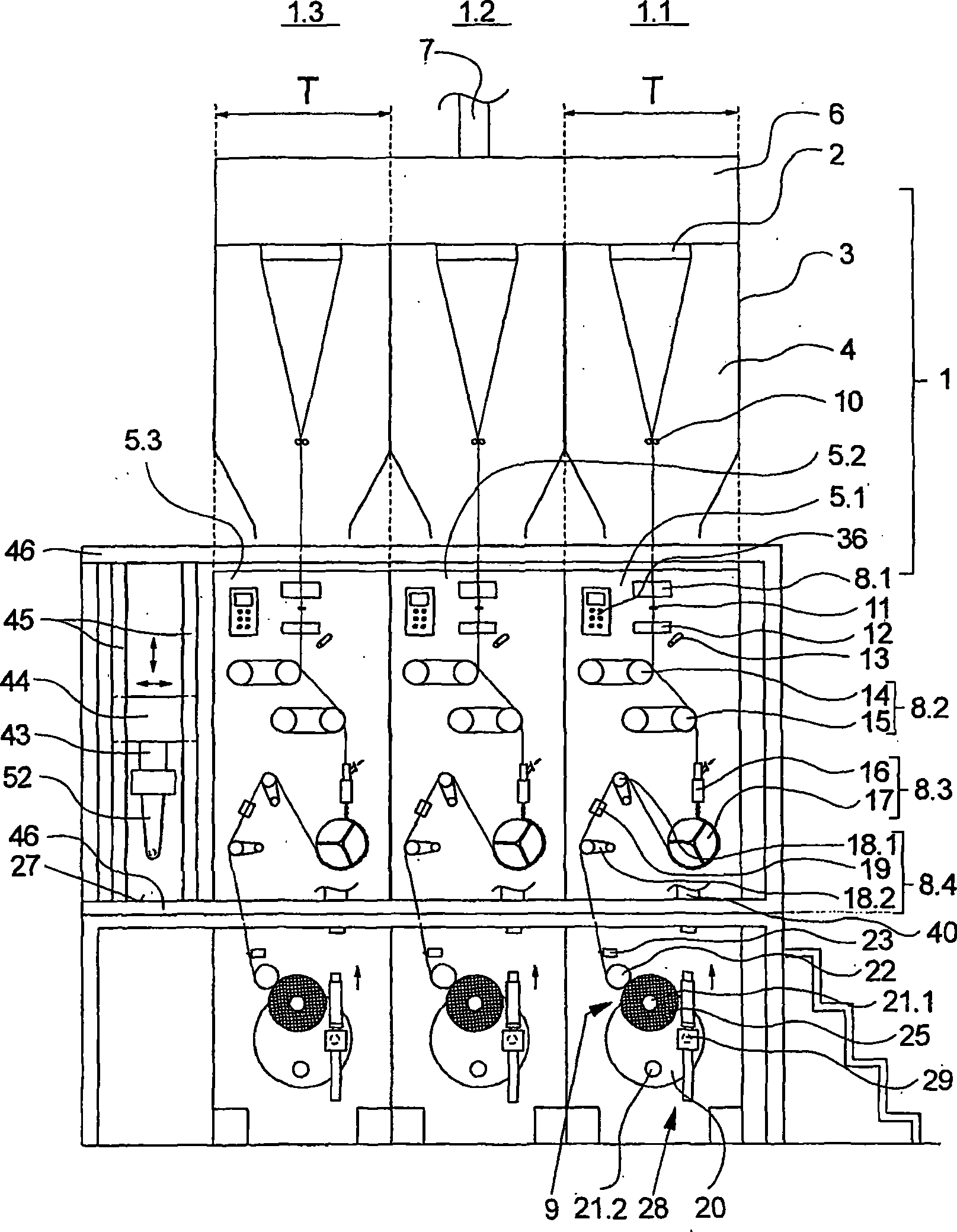
[0031] exist figure 1 and 2 A first embodiment of a spin-draw-crimp texturing machine according to the invention is shown in . exist figure 1 The front view of the spinning-stretching-crimping texturing machine is schematically shown in , while in figure 2 Its side view is schematically shown in . The following description applies to both figures as long as one figure is not explicitly identified.

[0032] In this embodiment, the spinning-drawing-crimp texturing machine is made up of a spinning device 1 and a plurality of machine modules arranged below the spinning device 1, wherein in this embodiment, three side-by-side Set up machine modules 5.1, 5.2 and 5.3. The machine modules 5.1, 5.2 and 5.3 contain a plurality of processing units 8 for drawing and texturing the filaments and a winding unit 9 for winding the filaments.

[0033]The spinning device 1 is divided into a plurality of spinning stations 1.1, 1.2 and 1.3, each spinning station being assigned a machine mod...


PUM


Abstract

The invention relates to a spinning, drawing and texturing machine for producing curled threads, said machine comprising a spinning unit and several machine modules that are allocated to the spinning unit. Each of said machine modules has several processing assemblies for drawing and curling one of the threads and a spooling unit for winding the thread. The machine modules are arranged next to one another to form a longitudinal side of the machine, the processing assemblies and spooling units being held in relation to one another on the machine modules in such a way that a narrow machine partition of approximately <800 mm occurs on the longitudinal side of the machine. The spinning unit has one or more spinnerets and a spinning duct within the machine partition, said spinnerets being held in rows parallel to the longitudinal side of the machine. Respective spinning positions that combine to produce a thread are thus obtained for each machine module.

Description

technical field [0001] The invention relates to a spin-draw-crimp texturing machine for producing crimped filaments according to the preamble of claim 1 . Background technique [0002] A spin-draw-texturizer of this type is known, for example, from EP 0 718 424 A1. [0003] In the known spin-draw-texturing machines, the treatment units arranged below the spinning device for drawing and crimping the filaments and the winding units are respectively combined into individual machine modules. The treatment units are arranged in particular side by side in the machine module, so that an essentially horizontally oriented thread guide prevails on the machine module. Depending on the processing steps, very wide machine modules are therefore required, which leads to correspondingly large machine partitions. However, such a large machine subdivision has the disadvantage in principle, especially in the (production) process control of a single thread, that the spinning nozzles required ...

Claims


Application Information

Patent Timeline
Patent Type & Authority Applications(China)
IPC IPC(8): D01D13/00D01D13/02D01D7/00D02G1/02
CPCD01D5/16B65H67/064B65H54/70B65H2701/31D01D7/00B65H67/0405B65H67/048D02G1/0266D01D13/02B65H57/003B65H2551/13
Inventor F·莱内曼M·申肯S·卡立斯
Owner OERLIKON TEXTILE GMBH & CO KG
Why Eureka
Try Eureka