Fluid bearing device and its manufacturing method

A technology of fluid bearings and bearing sleeves, applied in bearings, bearing components, shafts and bearings, etc., can solve problems such as dimensional tolerances, deterioration of rotation accuracy, and difficult positioning, and achieve the effects of excellent load capacity, easy assembly, and easy precision

A technology of fluid bearings and bearing sleeves, applied in bearings, bearing components, shafts and bearings, etc., can solve problems such as dimensional tolerances, deterioration of rotation accuracy, and difficult positioning, and achieve the effects of excellent load capacity, easy assembly, and easy precision

CN101438068AInactive Publication Date: 2009-05-20NTN CORP

Image

  • Fluid bearing device and its manufacturing method
  • Fluid bearing device and its manufacturing method
  • Fluid bearing device and its manufacturing method

Examples


Embodiment Construction

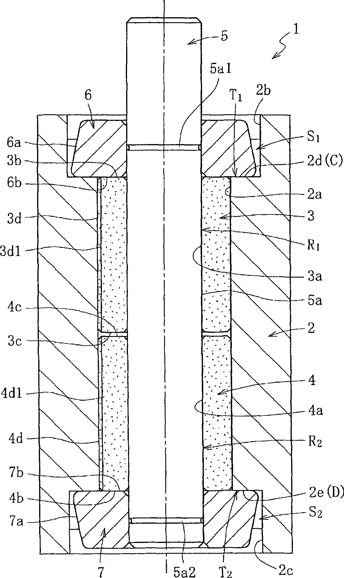
[0072] Next, embodiments of the hydrodynamic bearing device and its manufacturing method according to the present invention will be described based on the drawings. In addition, the "up and down" directions described below merely represent the up and down directions in each figure for convenience, and therefore do not limit the installation direction and usage of the fluid bearing device.

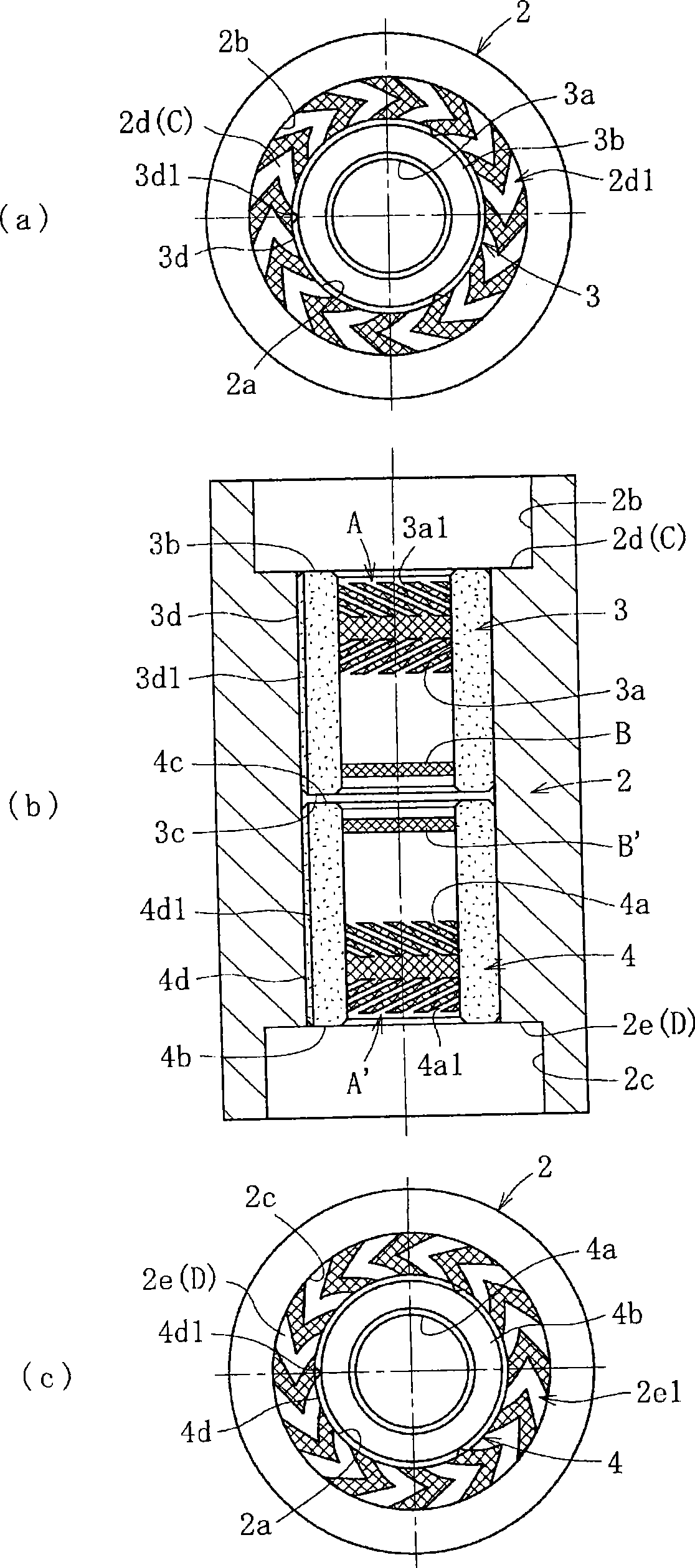
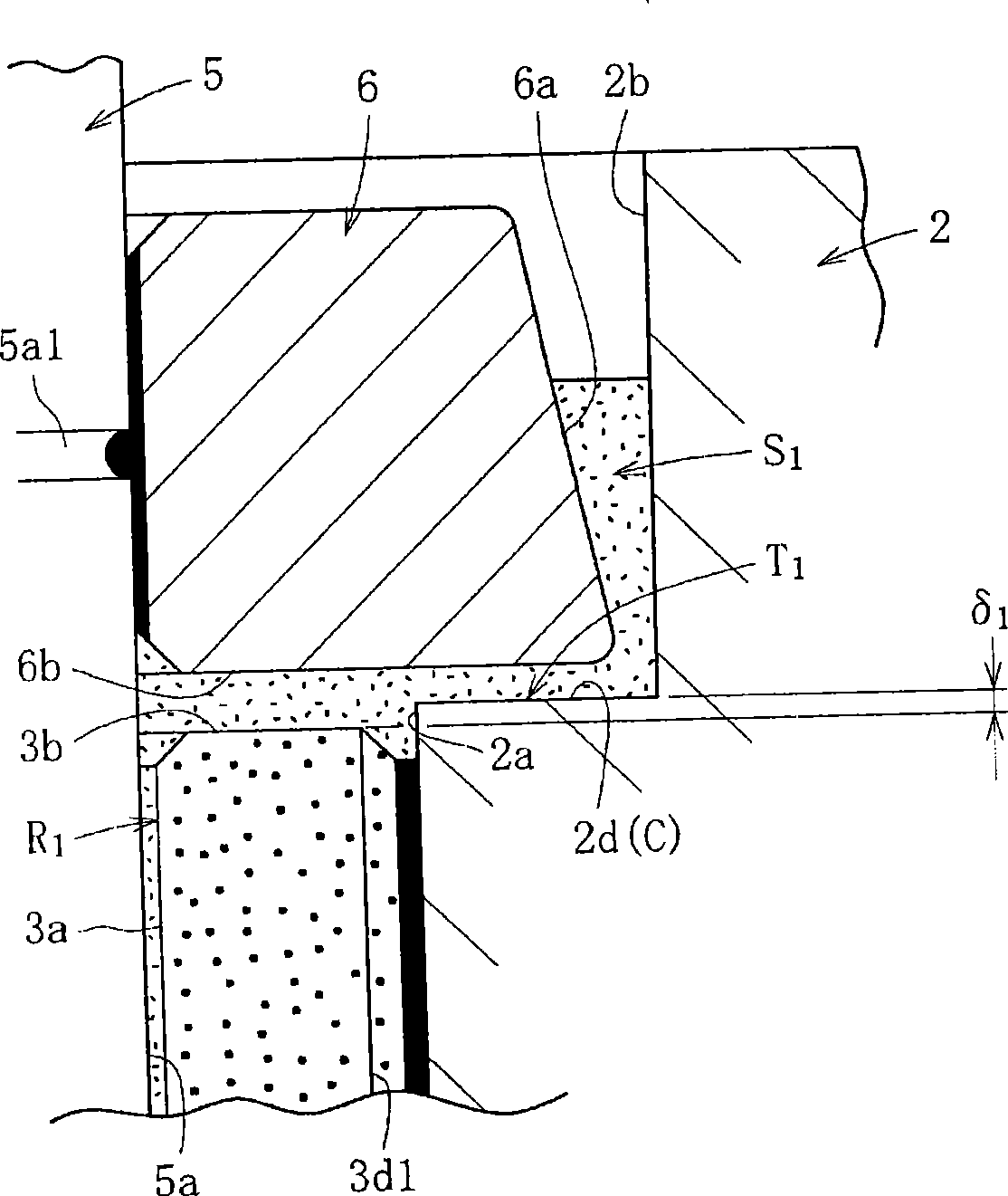
[0073] figure 1 The fluid bearing device 1 of the first embodiment is shown. This fluid bearing device 1 is incorporated into, for example, a spindle motor for HDD and used. This fluid bearing device 1 has the following structural components: a housing 2; a plurality of, here two, bearing sleeves (the first bearing sleeve 3 and the second bearing sleeve 4) fixed to the housing 2; inserting the two bearing sleeves 3, shaft member 5 on the inner periphery of shaft member 4; and seal members 6 and 7 as protrusions protruding from the outer diameter side of shaft member 5 .

[0074] The det...


PUM


Abstract

To provide a fluid bearing device in which a bearing sleeve can be easily assembled to a housing and which has excellent moment rigidity. [MEANS FOR SOLVING THE PROBLEMS] This fluid bearing device (1) comprises radial bearing parts (R1, R2) and thrust bearing parts (T1, T2). Thrust bearing surfaces (C, D) are provided on the first and second step surfaces (2d, 2e) of the housing (2) respectively. The thrust bearing parts (T1, T2) are formed between the thrust bearing surfaces (C, D) and the end surfaces (6b, 7b) of seal members (6, 7) projecting to the outer diameter side of a shaft member (5).

Description

technical field [0001] The present invention relates to a fluid bearing device and a method of manufacturing the same. Background technique [0002] A fluid bearing device supports a shaft member on a rotating member using a lubricating film of fluid generated in a bearing gap. This fluid bearing device has the characteristics of high-speed rotation, high rotation accuracy, and low noise. In recent years, it has been used as a bearing device for electric motors that firstly mount information equipment on various electrical appliances, and more specifically, as a magnetic disk such as HDD. Devices, CD-ROM, CD-R / RW, DVD-ROM / RAM and other optical disc devices, MD, MO and other optical disk devices, such as spindle motors, laser printers (LBP) polygon scanner motors, projector color film motors, Bearing devices for electric motors such as fan motors are preferably used. [0003] For example, as a fluid bearing device equipped with a spindle motor for a disk drive, Figure 14 T...

Claims


Application Information

Patent Timeline
20 May 2009
Publication
CN101438068A
IPC
F16C17/10; F16C35/02
Inventors
堀政治; 户田正明