Method for replacing guide blade of high-efficient powder sorter

A guide vane and replacement method technology, which is applied to chemical instruments and methods, solid separation, and separation of solids from solids with airflow, etc. It can solve the problems of long production line shutdown time, increased maintenance workload, and increased shutdown losses. , to achieve the effect of reducing maintenance costs, saving labor and time, and improving maintenance effects

Active Publication Date: 2009-05-27
ANSHAN IRON & STEEL GROUP CORPORATION
View PDF0 Cites 4 Cited by
  • Summary
  • Abstract
  • Description
  • Claims
  • Application Information

AI Technical Summary

Problems solved by technology

Such a structure can adjust the angle when needed, but it also leads to the need to remove the transmission system and the top cover of the housing on the upper part of the guide vane, so that the socket sleeve can be plugged on the socket shaft from top to bottom. , thus greatly increasing the maintenance workload and wasting a lot of labor
At the same time, it causes the production line to stop production for too long, which increases the loss of downtime.

Method used


Image

  • Method for replacing guide blade of high-efficient powder sorter
  • Method for replacing guide blade of high-efficient powder sorter
  • Method for replacing guide blade of high-efficient powder sorter

Examples


Embodiment Construction

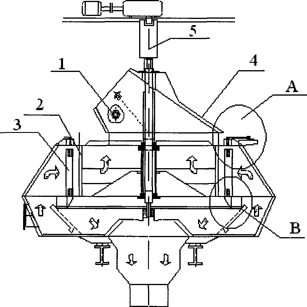
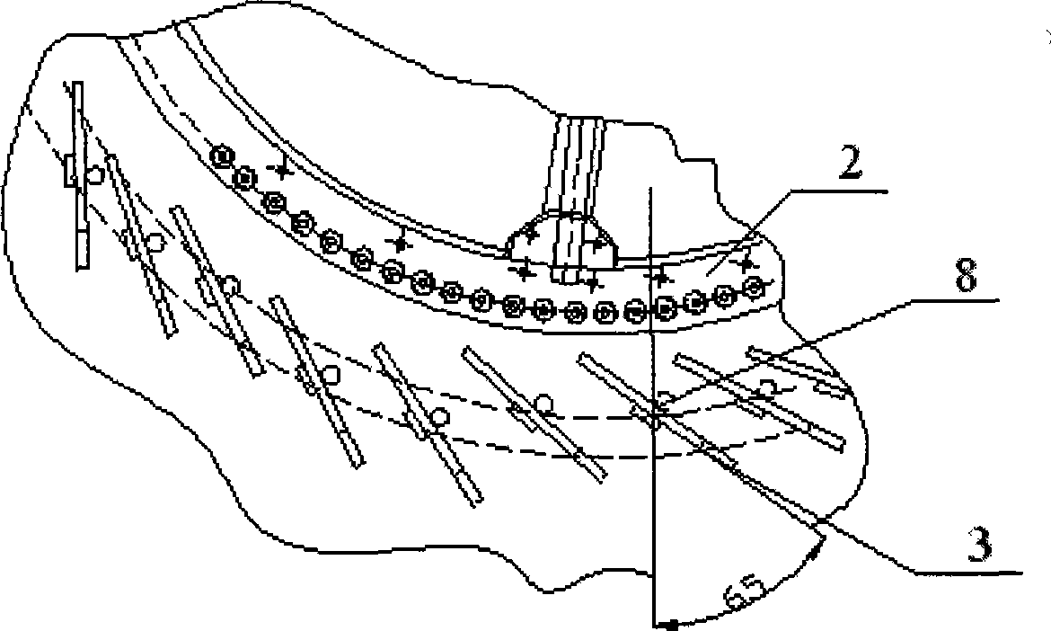
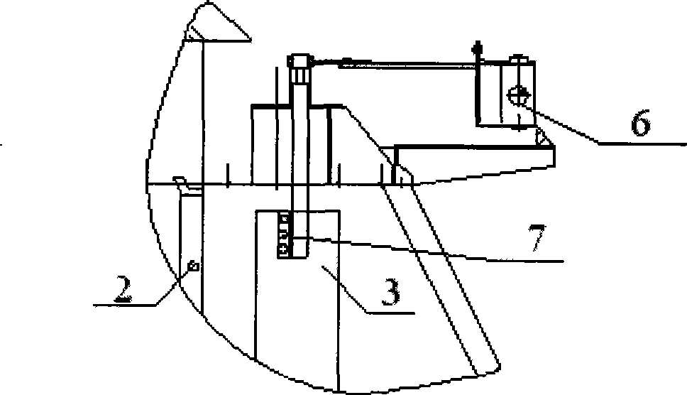
[0013] The embodiment of the present invention takes the replacement of the guide vanes of the RMS435 high-efficiency powder separator as an example, please refer to the attached Figure 1~4 . In the figure, 1 is the inspection port, 2 is the rotating blade, 3 is the vane of the guide vane, 4 is the top cover of the housing, 5 is the transmission system, 6 is the angle adjustment device, 7 is the connecting rod bolt, 8 and 9 are the socket respectively sleeve and socket shaft. Parts A and B in the figure are the upper and lower coupling mechanisms of the guide vanes respectively.

[0014] Before replacing the guide vanes, all 64 guide vanes are made separately according to the size of the original drawing, that is, the jack sleeve 8 at the bottom of the guide vanes and the vanes 3 are made separately, and then one of the vanes is decomposed into the main vane 31, the upper vane Side sub-blade 32 and lower side sub-blade 33 three parts, as attached Figure 5 shown.

[0015]...


PUM


Abstract

The invention provides a method for replacing a guide wheel bucket of a high-efficiency powder concentrator, which is characterized in that a jack sleeve arranged at the bottom of the guide wheel bucket is changed to be welded and assembled after installation, and the guide wheel bucket is installed in a horizontal way; the method comprises the steps: (1) vanes and the jack sleeve of the new guide wheel bucket are manufactured in a detachable way, and one vane is divided into a main vane, an upper side sub-vane and a lower side sub-vane; (2) part of rotating vanes are disassembled, and the guide wheel bucket is dismounted; (3) the jack sleeve is installed on a jack shaft, the main vane of the divided vane is installed on a connecting rod bolt and is welded and assembled with the jack sleeve; (4) other vanes are sequentially installed and is welded and assembled with the jack sleeve one by one; (5) the upper side sub-vane and the lower side sub-vane are respectively welded on the main vane. The method can be used for replacing the guide wheel bucket without dismounting a drive system at the upper part and a coping of a shell, so as to save a great deal of manpower and time, and the benefit is considerable.

Description

technical field [0001] The invention belongs to the maintenance method of the high-efficiency powder separator, which is the final control equipment of powdery product quality, and in particular relates to the replacement method of the guide vane of the high-efficiency powder separator. Background technique [0002] Manufacturers in the cement and refractory industries mainly produce powder products. The main determinant of product quality is the particle size of the product. The high-efficiency powder separator is the final control equipment for the quality of powder products. Since all products are processed by the high-efficiency powder separator In screening, there is a common problem of guide vane and rotor blade wear, and the guide vane and rotor blade must be replaced if they are worn to a certain extent and affect product quality. The rotating blades can be replaced directly when the equipment is out of production, and the replacement of the guide vanes becomes a key...

Claims


Application Information

Patent Timeline
IPC IPC(8): B07B7/083B23P6/00
Inventor 苏兴文于庆浩胡光普吴立恩
Owner ANSHAN IRON & STEEL GROUP CORPORATION
Why Eureka
Try Eureka