Constant tension compensating mechanism

A compensation device and constant tension technology, applied in the direction of overhead lines, etc., can solve the problems of low transmission reliability, inconvenient installation, complex structure of the constant tension compensation device, etc., to save materials and processing costs, easy installation, and high reliability. Effect

Active Publication Date: 2009-05-27
KERN LIEBERS TAICANG
View PDF1 Cites 13 Cited by
  • Summary
  • Abstract
  • Description
  • Claims
  • Application Information

AI Technical Summary

Problems solved by technology

[0018] The purpose of the present invention is to solve the problems of complex structure, inconve...

Method used


Image

  • Constant tension compensating mechanism
  • Constant tension compensating mechanism

Examples


Embodiment Construction

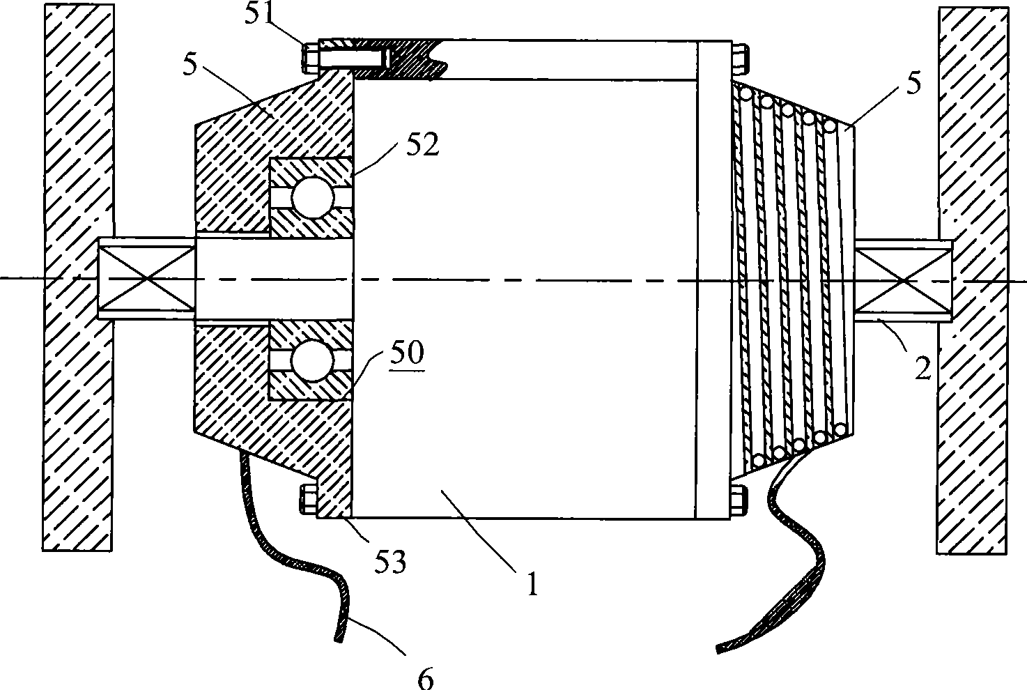
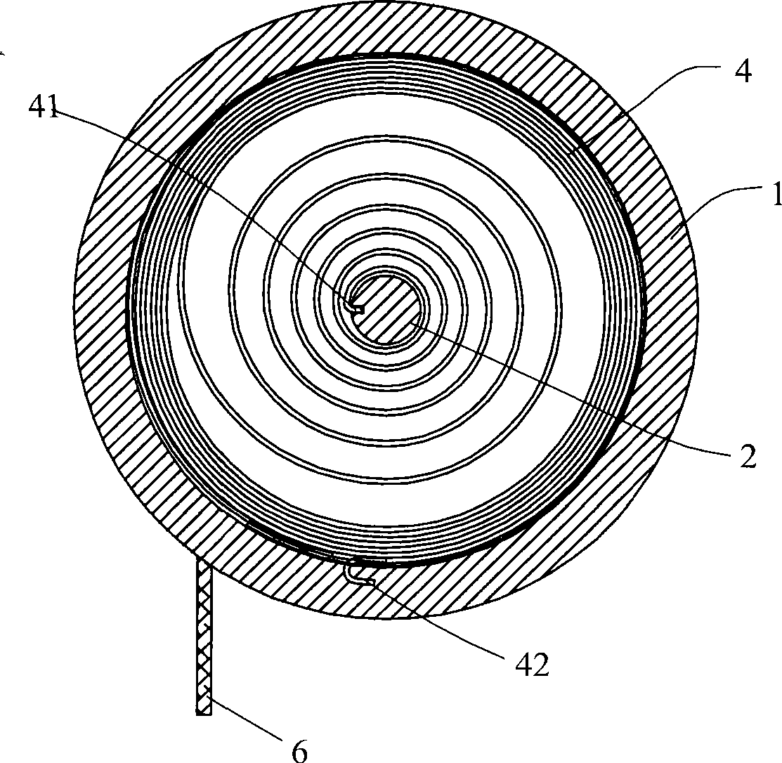
[0027] The constant tension compensation device of the present invention is as figure 1 , 2 As shown, it includes a housing 1 and a main shaft 2 that can rotate relative to the housing 1 . The plane scroll spring 4 is arranged between the housing 1 and the main shaft 2 , wherein the inner hook 41 of the plane scroll spring 4 is fixed on the main shaft 2 , and the outer hook 42 is fixed on the inner wall of the housing 1 .

[0028] from figure 2 , it can be seen that the cross-section of the housing 1 is circular, and steel pipes can be directly used for simple processing without special manufacturing. The number of planar scroll springs 4 in the casing 1 can be set in multiples according to requirements, and steel pipes of corresponding lengths are used according to the number of springs 4 .

[0029] The sheave 5 is fixedly mounted on the end of the housing 1, can rotate with the housing 1 relative to the main shaft 2, and doubles as an end cover to close the housing. In ...


PUM


Abstract

The invention relates to a constant tension compensating mechanism which comprises a shell, a main shaft that can rotate correspondingly to the shell, a plane volute spring arranged between the shell and the main shaft, and an involute compensating scored pulley; the constant tension compensating mechanism is characterized in that the compensating scored pulley is fixedly installed at the end part of the shell and is simultaneously taken as a close end cover of the shell, and a wire rope is wound on the involute compensating scored pulley. The scored pulley is installed on the shell and is not fixed with the main shaft, so that the main shaft and the scored pulley are not needed to be provided with key slots, thus guaranteeing the strength of the structures of the main shaft and the scored pulley; at the same time, as a bolt is adopted to connected the scored pulley and the shell, the installation is convenient, and the reliability is high. As scored pulley is simultaneously taken as the end cover, the special end cover can be left out, thus saving the materials and the processing cost.

Description

technical field [0001] The invention relates to a constant tension compensation device, in particular to a constant tension compensation device applicable to the technical field of rail transit power supply. Background technique [0002] The tension compensation device widely used in electrified track catenary is composed of concrete or cast iron weight and pulley block. Although this compensation device is simple in structure, it has the disadvantages of large volume, heavy weight, and easy swing and collision in case of wind. In order to solve this problem, No. 200510038591.2 invention patent proposes a constant tension compensation device. [0003] This invention patent discloses a constant tension compensation device, which includes a planar scroll spring installed on the base body, one end of which is relatively fixed to the base body, and the other end is relatively fixed to the main shaft. The main shaft is supported on the base body and is fixedly connected to the m...

Claims


Application Information

Patent Timeline
IPC IPC(8): B60M1/26
Inventor 张臻伟
Owner KERN LIEBERS TAICANG
Why Eureka
Try Eureka