Brake lamp fault monitoring apparatus and method

A technology of monitoring devices and brake lights, which is applied in the direction of signal devices, etc., to achieve the effect of driving safety

Inactive Publication Date: 2009-05-27
CHERY AUTOMOBILE CO LTD
View PDF0 Cites 7 Cited by
  • Summary
  • Abstract
  • Description
  • Claims
  • Application Information

AI Technical Summary

Problems solved by technology

[0004] The main purpose of the present invention is to solve the problem of rear-end collision accidents caused by the failure of the brake lights, and proposes an automatic light-on alternative that does not depend on the driver himself when the brake lights fail and the driver has a braking action The technical scheme of lamps and lanterns, in order to achieve the purpose of warning the car behind, can reduce the rear-end collision accident caused by the failure of the brake light to the greatest extent

Method used


Image

  • Brake lamp fault monitoring apparatus and method
  • Brake lamp fault monitoring apparatus and method

Examples


Embodiment Construction

[0014] The present invention will be specifically described below in conjunction with the accompanying drawings.

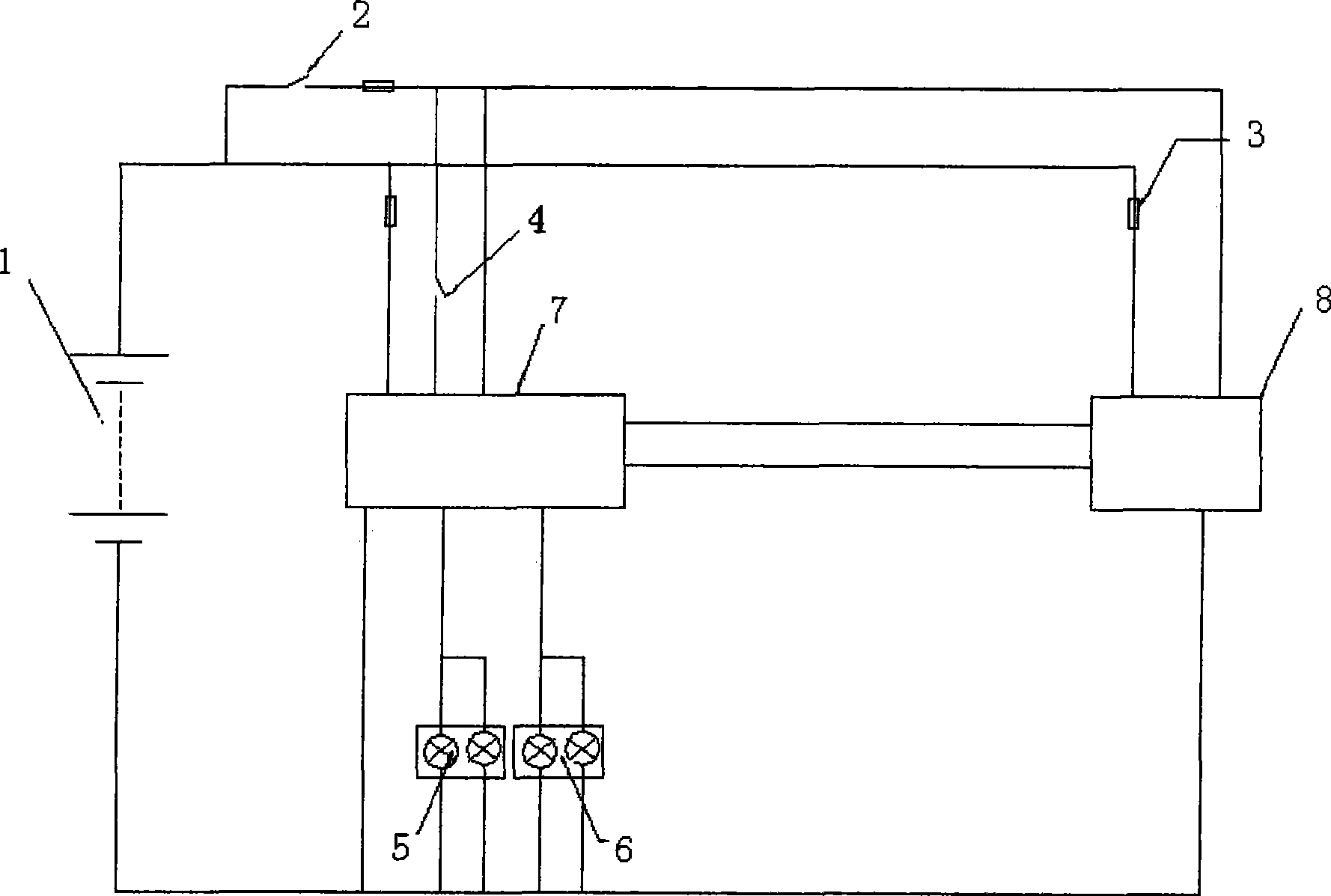
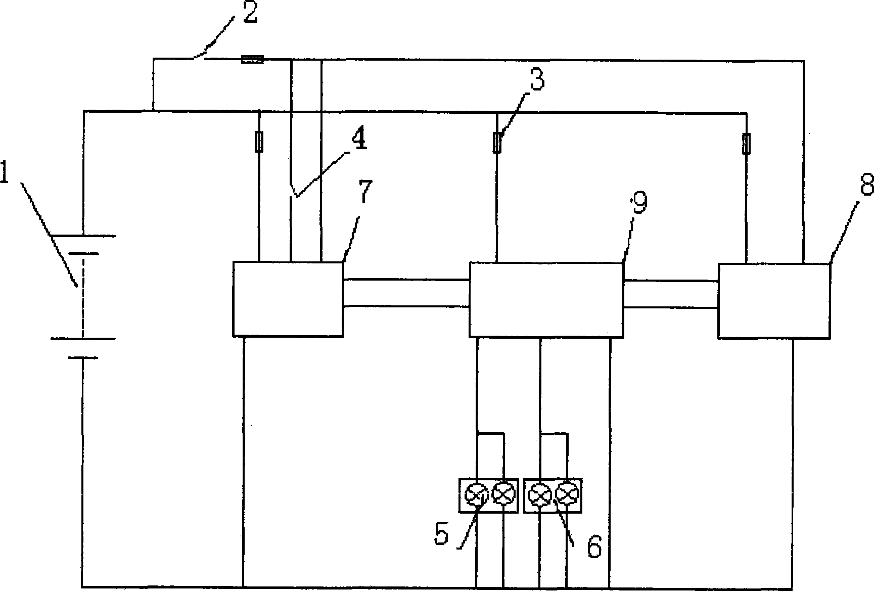
[0015] figure 1 The first embodiment of the present invention is shown, and the shown brake light control device mainly includes: a vehicle body controller 7, an instrument 8, an ignition switch 2, a battery 1, a fuse 3, a brake switch 4, a brake light 5, Rear fog lights6. The brake light 5 is directly controlled by the vehicle body controller, and the vehicle body controller 7 is connected to the instrument 9 through a bus.

[0016] Under normal conditions, when the ignition switch 2 is turned to the ON (open) gear, the brake switch 4 acts, and the vehicle body controller 7 collects the signal of the brake switch 4, processes it, drives the brake light 5, and turns the brake switch The normal information of the moving light 5 is transmitted to the instrument through the bus.

[0017] In the case of a failure of the brake light, the body controller detects the ...


PUM


Abstract

The invention discloses a brake lamp monitoring apparatus and a method using the monitoring apparatus for monitoring invalidation of brake lamps; the monitoring apparatus comprises a bodywork controller (7), a meter (8), a tappet switch (4), the brake lamps (5) and a rear fog lamp (6), wherein, the bodywork controller (7) is connected with a meter (9) by a bus and is used for detecting the state of the brake lamp (5); when one of the brake lamps is out of work, a brake fault indicating lamp arranged on the meter is caused to twinkle after the meter (8) receives the information. When the two brake lamps (5) are out of work at the same time, the fog lamp (6) is controlled to be lightened, and the brake fault indicating lamps on the meter (8) are simultaneously controlled to be lightened. The brake lamp monitoring apparatus can ensure the wiring to be simpler by adding a tail lamp driving module (9). By utilizing the technical proposal of the invention, the substitute proposal can be adopted after the self of the brake lamp has fault and is out of work; the brake lamp monitoring apparatus can automatically warn the succeeding vehicles, and simultaneously notice the driver that the brake lamps are out of work and need to be repaired as soon as possible by using the meter, thereby leading the drive to be safer.

Description

technical field [0001] The invention relates to a brake warning scheme, in particular to an alternative scheme after a brake light fails. Background technique [0002] On existing traditional vehicles, the brake light is generally connected in series with the brake switch. When the driver steps on the brake pedal, the brake switch will act accordingly to light the brake light; The moving lights go off. In some advanced vehicles with a bus system, the vehicle body control unit collects the brake signal, transmits the brake signal to the light control unit through the bus, and the light control unit drives the brake light. [0003] A problem with both solutions is that the brake lights do not come on when the brake lights themselves fail, and the driver does not know that the brake lights have failed. When the front vehicle brakes, the driver of the rear vehicle cannot know the braking intention of the driver of the front vehicle because there is no brake indicator signal, w...

Claims


Application Information

Patent Timeline
IPC IPC(8): B60Q11/00B60Q9/00
Inventor 石瑞林
Owner CHERY AUTOMOBILE CO LTD
Why Eureka
Try Eureka