
Compound type rotating axle seal

A rotating shaft, composite technology, applied in the direction of engine seals, engine components, mechanical equipment, etc., can solve the problems of low rigidity, unadjustable shaft seals, difficult to withstand high pressure for a long time, etc., to improve sealing and prolong service life. , the effect of increasing rigidity

Active Publication Date: 2009-05-27
ZHENJIANG DALI HYDRAULIC MOTOR
View PDF4 Cites 9 Cited by
  • Summary
  • Abstract
  • Description
  • Claims
  • Application Information

AI Technical Summary

Problems solved by technology

[0004] The Chinese patent “Compact High Pressure Rotary Shaft Sealing Ring” (Patent No. ZL L200620070646.8) that the applicant applied for earlier solved the problem of pressure-bearing sealing and compact structure, and the ability to withstand back pressure has far exceeded that of ordinary shaft seals. ; However, when the shaft seal is directly used for products with high-pressure medium communication (such as high-speed distribution cycloid hydraulic motors), its ability to withstand high pressure for a long time is insufficient
For this reason, another Chinese patent "back pressure high-pressure shaft seal" (patent No. ZL200620078011.2) that the applicant applied for earlier can solve the problem of high pressure resistance at the shaft seal that directly communicates with the high-pressure medium; There are non-adjustable, so it is still difficult to withstand high pressure for a long time
[0005] Search found that the U.S. Patent No. US5,213,343 discloses a shaft seal with support member and backing ring (Shaft seal with support member and backing ring), which adds a backing ring to the existing seal And the spacer between the back ring and the seal can reduce wear and prolong service life; but the pressure resistance of the shaft seal is not enough
Retrieval finds again, and the patent No. is US6,783, and the U.S. patent of 339B2 discloses a kind of hydraulic motor with shaft valve (hydraulic motor with a spool valve), and the shaft seal contained in this hydraulic motor is made up of combined seal, washer and floating The retaining ring is assembled together in the axial direction. The shaft seal can withstand high pressure, but the combined seal of the shaft seal has the disadvantages of low rigidity and poor sealing.

Method used


Image

  • Compound type rotating axle seal
  • Compound type rotating axle seal
  • Compound type rotating axle seal

Examples


Embodiment

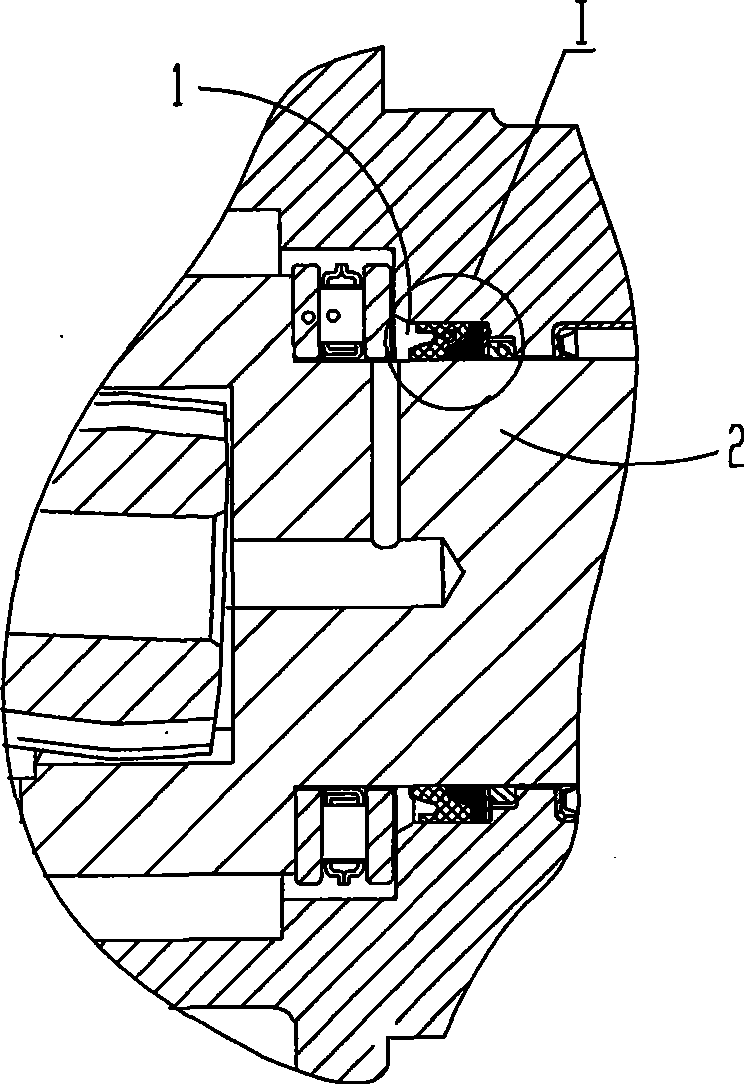
[0019] Such as figure 1 As shown, the composite rotating shaft of this embodiment is sealed and mounted between the housing hole 1 and the rotating shaft 2 of the high-speed distribution cycloid hydraulic motor.

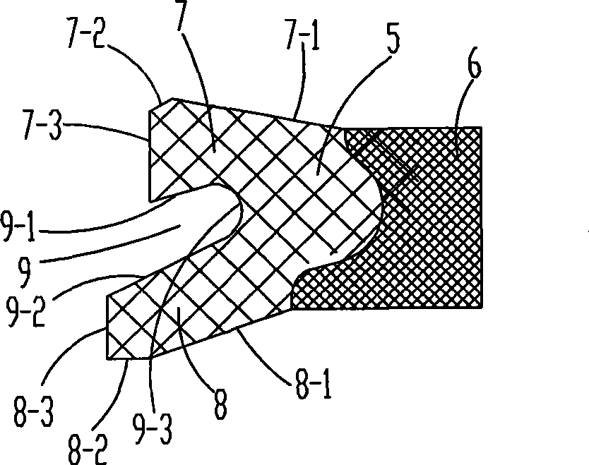
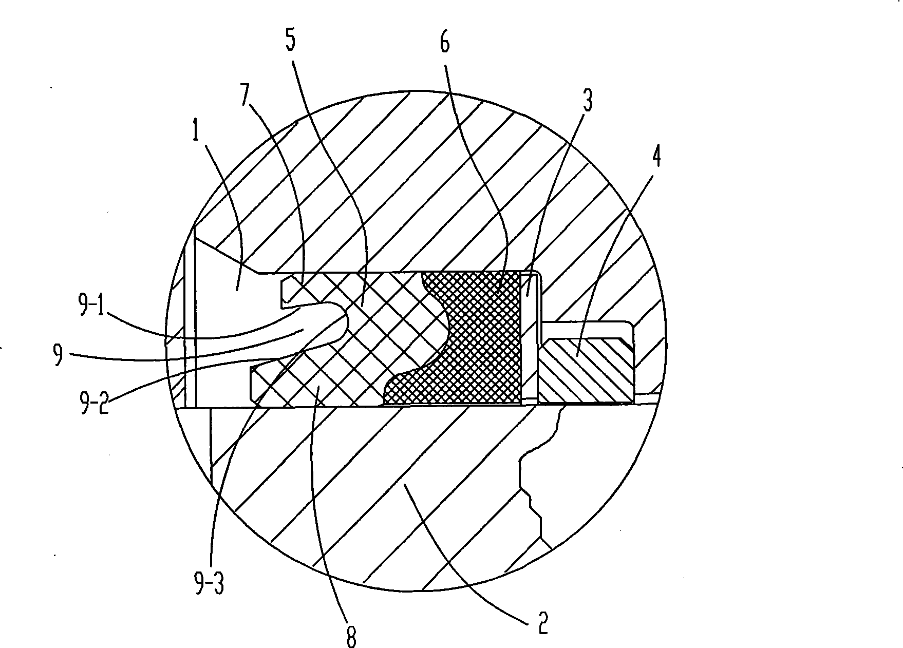
[0020] Such as figure 2 As shown, the composite rotary shaft seal includes a composite sealing body, a spacer ring 3 and a movable retaining ring 4 which are sequentially assembled together in the axial direction. The composite sealing body is composed of a rubber ring body 5 and a skeleton ring body 6 whose end faces are closely attached to each other, and the rubber ring body 5 forms an interference fit with the housing hole 1 and the rotating shaft 2 respectively. The rubber ring body 5 is formed with a lip structure facing the high-pressure medium in the axial direction. The lip structure is composed of an upper lip 7 abutting against the housing hole 1 , a lower lip 8 abutting against the rotating shaft 2 , and a notch 9 connecting the upper lip 7 and the low...


PUM

PropertyMeasurementUnit
Thicknessaaaaaaaaaa

Abstract

The invention relates to a composite type rotary shaft seal and belongs to the technical field of hydraulic and pneumatic sealing piece. The shaft seal comprises a composite sealing body, a spacing ring and a movable retaining ring which are embedded between a shell hole and a rotating shaft and are sequentially assembled together along the axial direction; the composite sealing body consists of a rubber ring body and a frame ring body of which end faces are tightly adhered; the rubber ring body is in interference fit with the shell hole and the rotating shaft respectively to form a lip structure facing towards a high-pressure medium along the axial direction; the lip structure consists of an upper lip clinging to the shell hole, a lower lip clinging to the rotating shaft and a recess part connected with the upper lip and the lower lip; the recess part consists of two sections of bevels and a section of cambered surface connected with two sections of the bevels; and the section of the frame ring body is of a U shape basically. The shaft seal can bear high pressure for a long time, obviously prolong the service life and remarkably improve sealing performance.

Description

technical field [0001] The invention relates to a sealing device, in particular to a high-pressure resistant sealing rotary sealing device used in hydraulic and pneumatic facilities, and belongs to the technical field of hydraulic and pneumatic seals. Background technique [0002] Skeleton rubber rotary shaft seal (hereinafter referred to as shaft seal) is a commonly used seal. This type of seal is usually used to seal the rotating surface in hydraulic and pneumatic transmission devices. Its basic structure can be found in the corresponding sealing technical manual. Usually Installed in an annular groove on a cylindrical surface. The rubber ring seals the rotating shaft, and the front and rear faces are respectively subjected to the isolated high and low pressure media. [0003] As far as the applicant knows, in hydraulic and pneumatic transmission parts, especially in products such as hydraulic pumps and hydraulic motors, the basic power output is rotational torque, so the...

Claims


Application Information

Patent Timeline
IPC IPC(8): F16J15/32F16J15/3232
Inventor 王志生张智敏潘骏王顺发翁爱光
Owner ZHENJIANG DALI HYDRAULIC MOTOR
Learn More