Free curved surface lens
A curved lens and free technology, applied in lighting and heating equipment, electrical components, circuits, etc., can solve the problems of not meeting the requirements of light distribution and changing the light distribution
- Summary
- Abstract
- Description
- Claims
- Application Information
AI Technical Summary
Problems solved by technology
Method used
Image

Examples
Embodiment 1
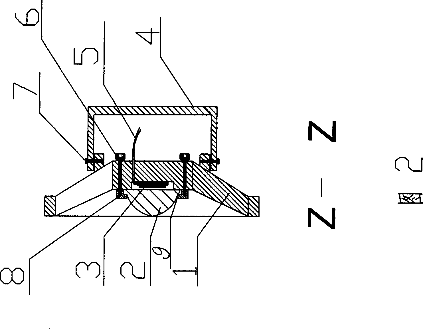
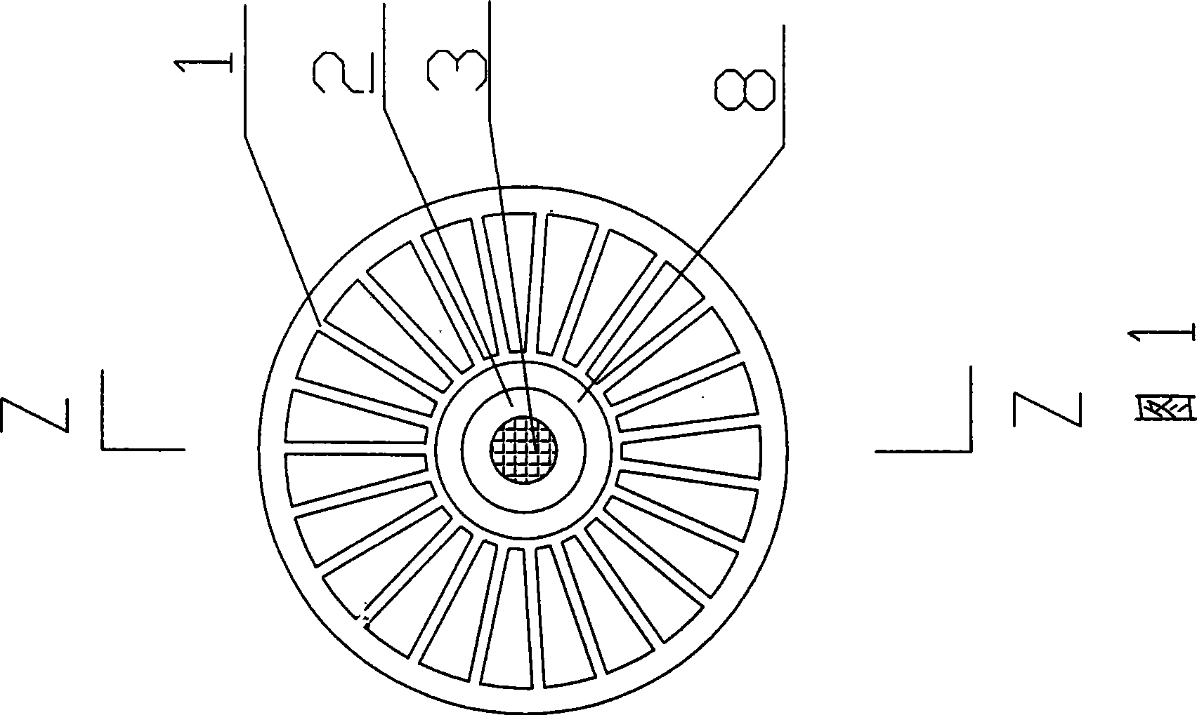
[0062] Embodiment 1 sees Fig. 1, Fig. 2, image 3 , Figure 4 , Figure 5 .
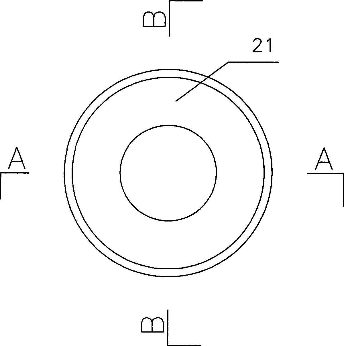
[0063]A free-form surface lens, which is used for lamps that use high-power LEDs in single-chip packages or multi-chip integrated packages as light sources. LED3 is fixed on the lamp body 1, and free-form surface lenses 21 are located in the direction of LED irradiation; The edge 9, the pressure ring 8 is pressed on the flange 9, and the bolt 6 is fixedly connected with the lamp body 1, and the LED3 is sealed between the lamp body and the free-form surface lens 2; the bolt 7 passes through the bracket 4 and is fixed on the rear side of the lamp body 1 Connection, the bracket 4 is rotationally connected with the lamp body 1; the wire 5 is connected to the terminal on the LED3 through the wire hole on the lamp body from the rear of the lamp body. The structure of the free-form surface lens is that the free-form surface lens 21 is a solid body, the bottom surface is flat, and the shape is circular. Th...
Embodiment 2
[0065] Example 2 see Figure 6 , Figure 7 , Figure 8 middle
[0066] The structure of the free-form surface lens is that the free-form surface lens 22 is a solid body with a flat bottom surface and a circular shape. Other structures are with embodiment 1.
[0067] Such a structure can cause the incident light to be refracted by the lens, and the light in the middle area will be diverged, and the light will be scattered to the periphery, so as to reduce the brightness of the central point, expand the irradiation area, and improve the uniformity of light distribution illuminated by the lamp. The curvature to achieve the preset light distribution effect. It is suitable for indoor and outdoor lighting of squares, roads, tunnels, factory workshops, mining areas, stadiums, theaters, landscapes and other large spaces.
Embodiment 3
[0068] Example 3 see Figure 9 , Figure 10 , Figure 11, Figure 12
[0069] The structure of the free-form surface lens is that the free-form surface lens 23 is a solid body, the bottom surface is flat, and the shape is circular. The light-emitting surface of the free-form surface lens 23 is three protrusions, and the height of the strip-shaped protrusion 231 in the middle is greater than that of the protrusions on both sides. 232 height; the raised parts are connected by a concave arc transition. Other structures are with embodiment 1.
[0070] Such a structure can make the direction of the refracted light in the middle area change smaller than that on the two sides after the incident light is refracted by the lens, and the angle of the refracted light in the direction of the two sides changes greatly. When the light increases, there is no obvious converging effect in the middle area, and the overall irradiation area is oblong, and the uniformity of light distribution in t...
PUM
 Abstract
Description
Claims
Application Information
 - R&D
- Intellectual Property
- Life Sciences
- Materials
- Tech Scout
- Unparalleled Data Quality
- Higher Quality Content
- 60% Fewer Hallucinations
Browse by: Latest US Patents, China's latest patents, Technical Efficacy Thesaurus, Application Domain, Technology Topic, Popular Technical Reports.
© 2025 PatSnap. All rights reserved.Legal|Privacy policy|Modern Slavery Act Transparency Statement|Sitemap|About US| Contact US: help@patsnap.com