Touch control panel and liquid crystal display panel

A liquid crystal display panel, touch panel technology, applied in static indicators, nonlinear optics, optics, etc., can solve other problems such as attachment, and achieve the effect of thin thickness

Inactive Publication Date: 2009-05-27
WINTEK CORP
View PDF0 Cites 27 Cited by
  • Summary
  • Abstract
  • Description
  • Claims
  • Application Information

AI Technical Summary

Problems solved by technology

[0005] The present invention provides a touch panel, which has a light filtering function, to solve the problem that the touch panel in the color touch display panel needs to be additionally attached to the color display panel

Method used


Image

  • Touch control panel and liquid crystal display panel
  • Touch control panel and liquid crystal display panel
  • Touch control panel and liquid crystal display panel

Examples


no. 1 example

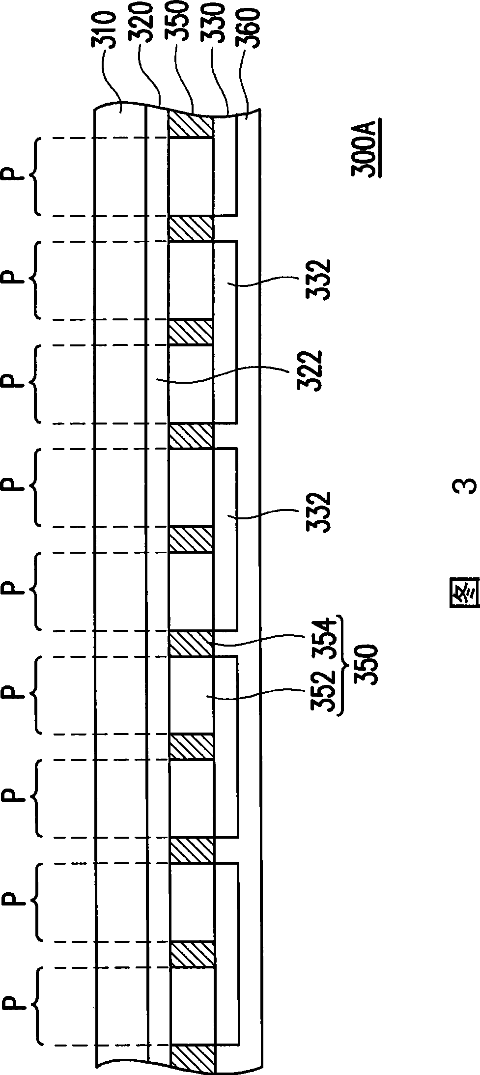
[0027] FIG. 3 is a schematic diagram of a touch panel according to a first embodiment of the present invention. Please refer to FIG. 3 , a touch panel 300A includes a substrate 310, a first electrode layer 320, a second electrode layer 330, a first dielectric layer (350) and a second dielectric layer 360, wherein the first dielectric layer (350) For example, the color filter layer 350 . The first electrode layer 320 is disposed on the substrate 310 , and the second electrode layer 330 is disposed above the first electrode layer 320 . The color filter layer 350 is disposed between the first electrode layer 320 and the second electrode layer 330 , and the second dielectric layer 360 is disposed on the second electrode layer 330 . Meanwhile, the second electrode layer 330 is located between the color filter layer 350 and the second dielectric layer 360 .

[0028] In this embodiment, the thickness of the first dielectric layer, that is, the color filter layer 350 will affect the...

no. 2 example

[0038] FIG. 7 is a schematic diagram of a touch panel according to a second embodiment of the present invention. Please refer to FIG. 7, the touch panel 700 is similar to the touch panel 300A, the difference is that the second dielectric layer of the touch panel 700 is a color filter layer 760, while the first dielectric layer 750 is not a color filter layer. The touch panel 700 can have many changes like the touch panel 300A, for example, a flat layer (not shown) is arranged on the color filter layer 760 of the touch panel 700, or the color filter layer forming the second dielectric layer A grounded conductive layer (not shown) is disposed on the filter layer 360 , and a third dielectric layer (not shown) is disposed on the grounded conductive layer (not shown). In addition, the touch panel 700 may further include a protection layer (not shown), which is disposed between the second electrode layer 330 and the color filter layer 760 .

[0039] In other embodiments, the first...


PUM

PropertyMeasurementUnit
thicknessaaaaaaaaaa
thicknessaaaaaaaaaa

Abstract

The invention discloses a touching control panel with the optical filtering function, comprising a base plate, a first electrode layer, a second electrode layer, a first dielectric layer and a second dielectric layer. The first electrode layer is arranged on the base plate and the second electrode layer is arranged on top of the first electrode layer. The first dielectric layer is between the first electrode layer and the second electrode layer. The second dielectric layer is arranged on the second electrode layer. Simultaneously, the second electrode layer is between the first dielectric layer and the second dielectric layer, wherein one of the first dielectric layer and the second dielectric layer is a colorful filter layer. The invention also provides a liquid crystal display panel taking the touching control panel as the color filter.

Description

technical field [0001] The present invention relates to a touch panel and a liquid crystal display panel, and in particular to a touch panel with light filtering function and a colorful liquid crystal display panel with touch function. Background technique [0002] In today's information society, human beings are increasingly dependent on electronic products. Electronic products such as mobile phones, handheld PCs, Personal Digital Assistants (PDAs) or smart phones can be seen everywhere around our lives. In order to allow users to have a larger visual image and provide a more convenient operation mode in a limited volume, some electronic products combine a touch panel and a display panel to form a color touch display panel. [0003] FIG. 1 shows a conventional color touch display panel. Referring to FIG. 1 , the color touch display panel 100 includes a display panel 110 and a touch panel 120 , wherein the touch panel 120 is bonded to the display panel 110 through a double...

Claims


Application Information

Patent Timeline
Patent Type & Authority Applications(China)
IPC IPC(8): G02F1/133G02F1/1335G02F1/1333G02F1/1362
Inventor 郭建忠王文俊
Owner WINTEK CORP
Why Eureka
Try Eureka