Double-frequency fusion antenna array, common-mode suppression method and communication equipment

An antenna array and high-frequency antenna technology, applied in the directions of antenna, antenna coupling, antenna components, etc., can solve the problems of beam width widening and low-frequency antenna gain reduction, etc., to achieve stable pattern, high gain, and novel radiator structure Effect

Active Publication Date: 2021-03-09
SOUTH CHINA UNIV OF TECH
View PDF6 Cites 5 Cited by
  • Summary
  • Abstract
  • Description
  • Claims
  • Application Information

AI Technical Summary

Problems solved by technology

However, in the vertical oscillator dual-frequency fusion antenna array, there will be low-frequency common-mode current on the high-frequency oscillator, which will reduce the gain of the low-frequency antenna and widen the beam width.

Method used


Image

  • Double-frequency fusion antenna array, common-mode suppression method and communication equipment
  • Double-frequency fusion antenna array, common-mode suppression method and communication equipment
  • Double-frequency fusion antenna array, common-mode suppression method and communication equipment

Examples


Embodiment 1

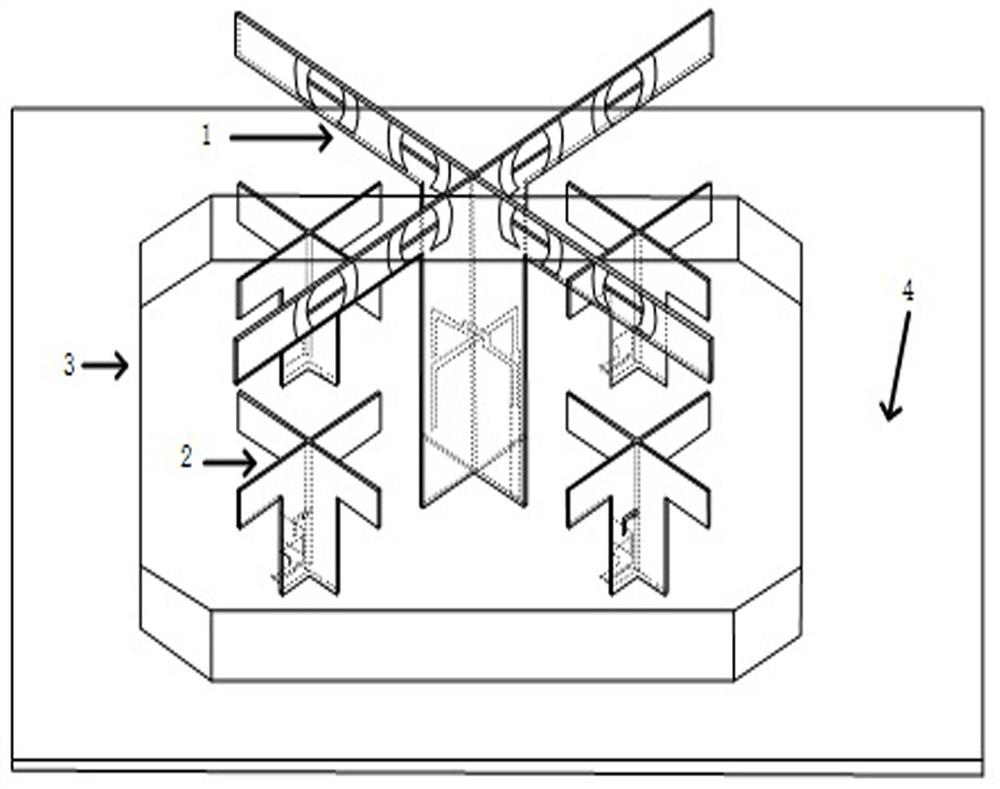
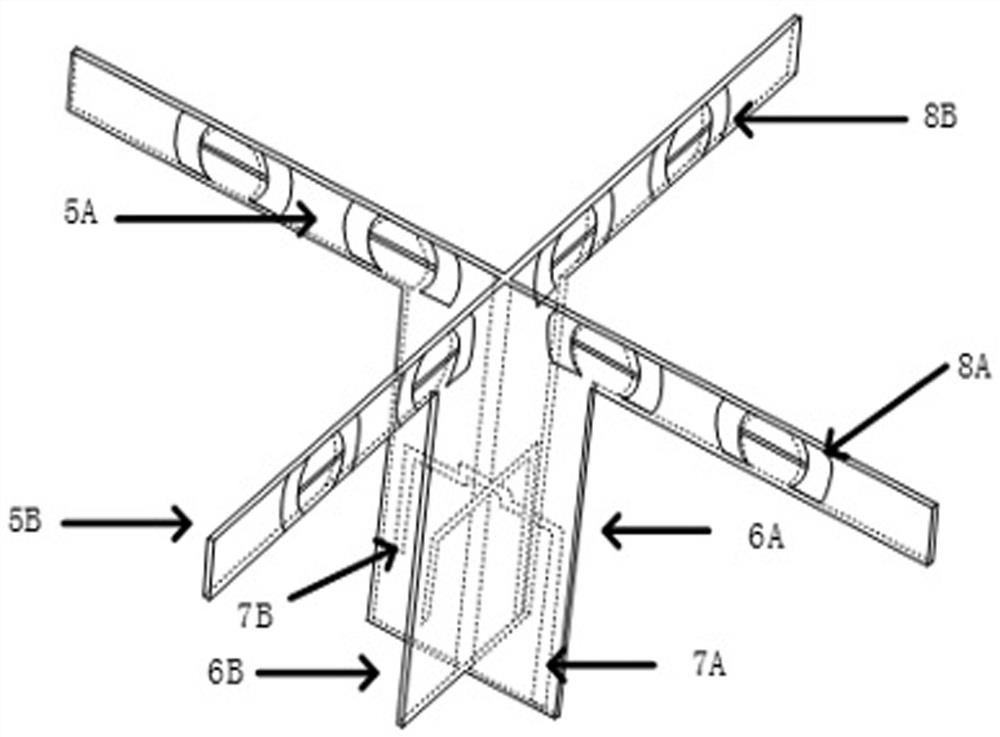
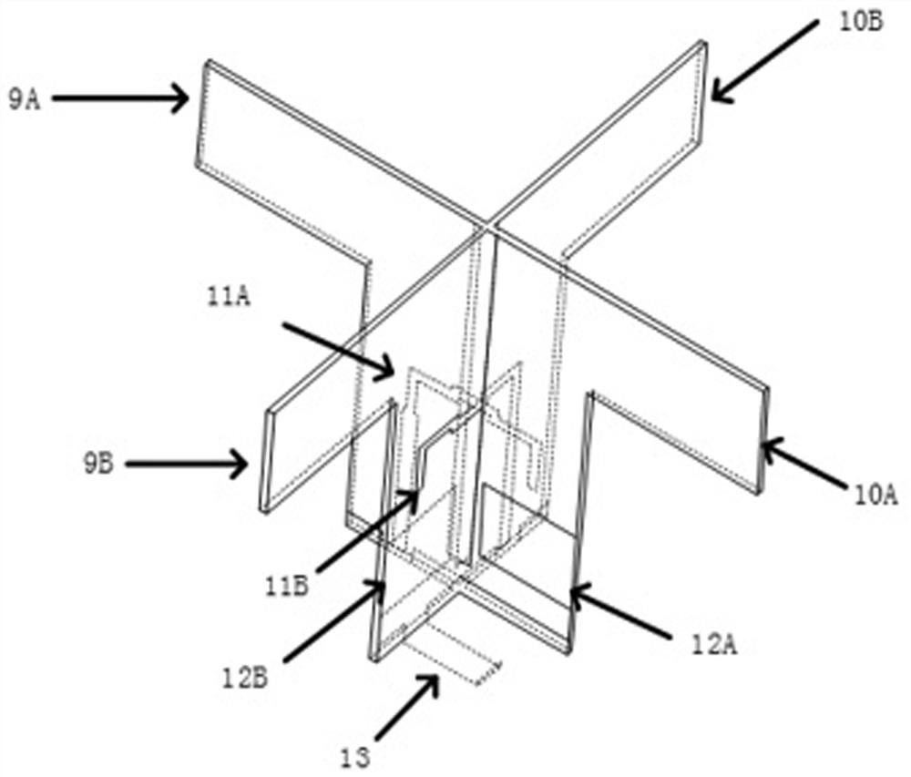
[0032] Such as figure 1 As shown, a dual-frequency fusion antenna array is a symmetrical structure, including a low-frequency antenna 1 with a working frequency band of 690-960 MHz, four high-frequency antennas 2 with a working frequency band of 1700-2700 MHz, a metal cylinder 3 and a reflector 4, The low-frequency antenna 1 and the high-frequency antenna 2 are all vertically above the reflector 3, the low-frequency antenna 1 is surrounded by four high-frequency antennas 2, and the high-frequency antenna stands below the low-frequency antenna, and the four high-frequency antennas are surrounded by four high-frequency antennas. The antenna 2 is symmetrical about the central axis of the low-frequency antenna 1. The longitudinal distance between the low-frequency antenna 1 and each high-frequency antenna 2 unit is 57.5mm, and the transverse distance is 62.5mm. Both the high-frequency antenna and the low-frequency antenna are arranged in the metal cylinder, and are symmetrical wit...

Embodiment 2

[0052] A common mode suppression method. During the feeding process of the low-frequency antenna, the high-frequency antenna will have an induced current, and the high-frequency antenna will further generate radiation. When the size of the high-frequency antenna is a quarter of the wavelength of the radiation frequency point, its The radiation acts as a monopole, which cancels out the low frequency radiation.

Embodiment 3

[0054] A communication device, including the dual-frequency fusion antenna array as described in Embodiment 1. The dual-frequency fusion antenna array makes the high and low frequency antennas share one antenna radiation aperture, which greatly improves the space utilization rate, and the bandwidth covers 690-960MHz and 1700-2700MHz, which meets the needs of GSM and 2G, 3G, 4G systems for base station antennas. The antenna array solves the problem of common mode interference between the high and low frequencies and the scattering of the high frequency signal by the low frequency antenna during the dual frequency fusion of the vertical oscillator.


PUM


Abstract

The invention discloses a double-frequency fusion antenna array, a common-mode suppression method and communication equipment, and the antenna array comprises a low-frequency antenna and a high-frequency antenna, the low-frequency antenna and the high-frequency antenna are vertically disposed on a reflection plate, the high-frequency antenna is symmetrically disposed around the low-frequency antenna, and the high-frequency antenna comprises two crossed high-frequency dielectric substrates. One side of each high-frequency dielectric substrate is provided with a high-frequency radiation oscillator, the other side of each high-frequency dielectric substrate is provided with a high-frequency feeder structure, two high-frequency radiation oscillators respectively comprise a high-frequency floorrectangular groove, and one high-frequency radiation oscillator further comprises a high-frequency floor extension structure. The antenna array solves the problem of mutual coupling between differentantennas, and has the advantages of large bandwidth, novel structure and stable radiation pattern.

Description

technical field [0001] The invention relates to the field of mobile communication, in particular to a dual-frequency fusion antenna array, a common-mode suppression method and communication equipment. Background technique [0002] With the rapid development of mobile communication technology, the development and utilization of new frequency bands is particularly important. As an important part of the mobile communication system, the base station antenna is the gateway for direct communication between mobile terminals such as mobile phones and the base station, and it is also the gateway for wireless communication systems to achieve frequency multiplexing and diversity. An important carrier of technologies such as reception. At present, there are GSM, 2G, 3G, and LTE (4G) systems in China. The GSM900 system uses 890-960MHz, the CDMA800 system uses 825-880MHz, the 2G system uses 1710-1550MHz, and the 3G system uses the frequency band 1550-2170MHz. , The LTE (4G) system uses 2...

Claims


Application Information

Patent Timeline
Patent Type & Authority Applications(China)
IPC IPC(8): H01Q1/38H01Q1/50H01Q1/52H01Q5/10H01Q5/307H01Q21/30
CPCH01Q1/38H01Q1/50H01Q1/523H01Q21/30H01Q5/10H01Q5/307
Inventor 李融林肖蓓崔悦慧
Owner SOUTH CHINA UNIV OF TECH
Why Eureka
Try Eureka