Eureka AIR delivers breakthrough ideas for toughest innovation challenges, trusted by R&D personnel around the world.

Electro-rheological fluid brake and actuator devices and orthotic devices using the same

An electro-rheological fluid and braking device technology, applied in the fields of portable orthoses, cam pivots, and electro-rheological fluid actuators, can solve the problems of increasing overall size, cost and weight, bulky devices, hindering applications, etc.

Inactive Publication Date: 2009-05-27
NORTHEASTERN UNIV
View PDF0 Cites 41 Cited by
  • Summary
  • Abstract
  • Description
  • Claims
  • Application Information

AI Technical Summary

Problems solved by technology

These devices are often bulky and inconvenient, which prevents their application and increases overall size, cost and weight due to the inclusion of active components

Method used


Image

  • Electro-rheological fluid brake and actuator devices and orthotic devices using the same
  • Electro-rheological fluid brake and actuator devices and orthotic devices using the same
  • Electro-rheological fluid brake and actuator devices and orthotic devices using the same

Examples


Embodiment Construction

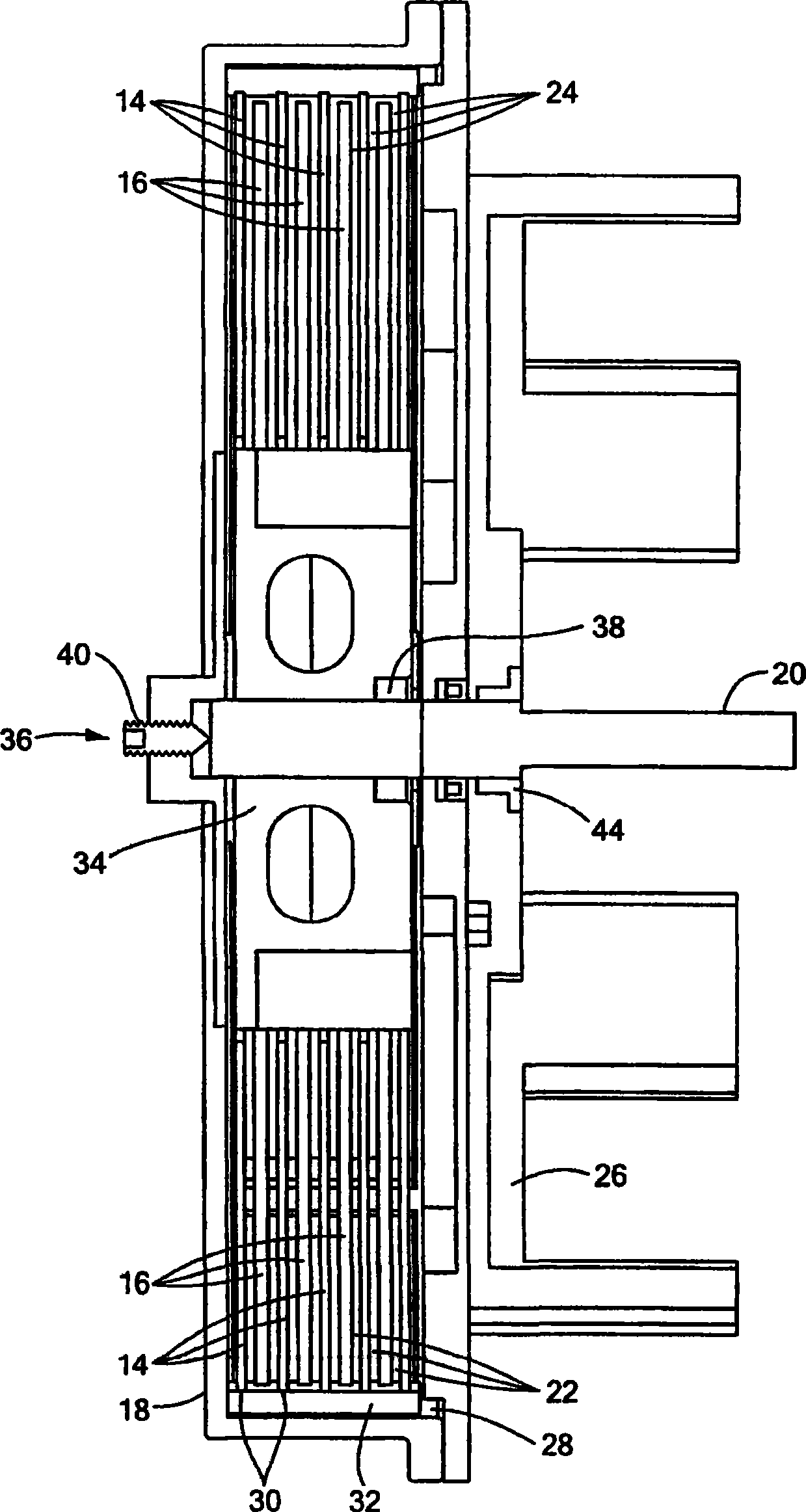
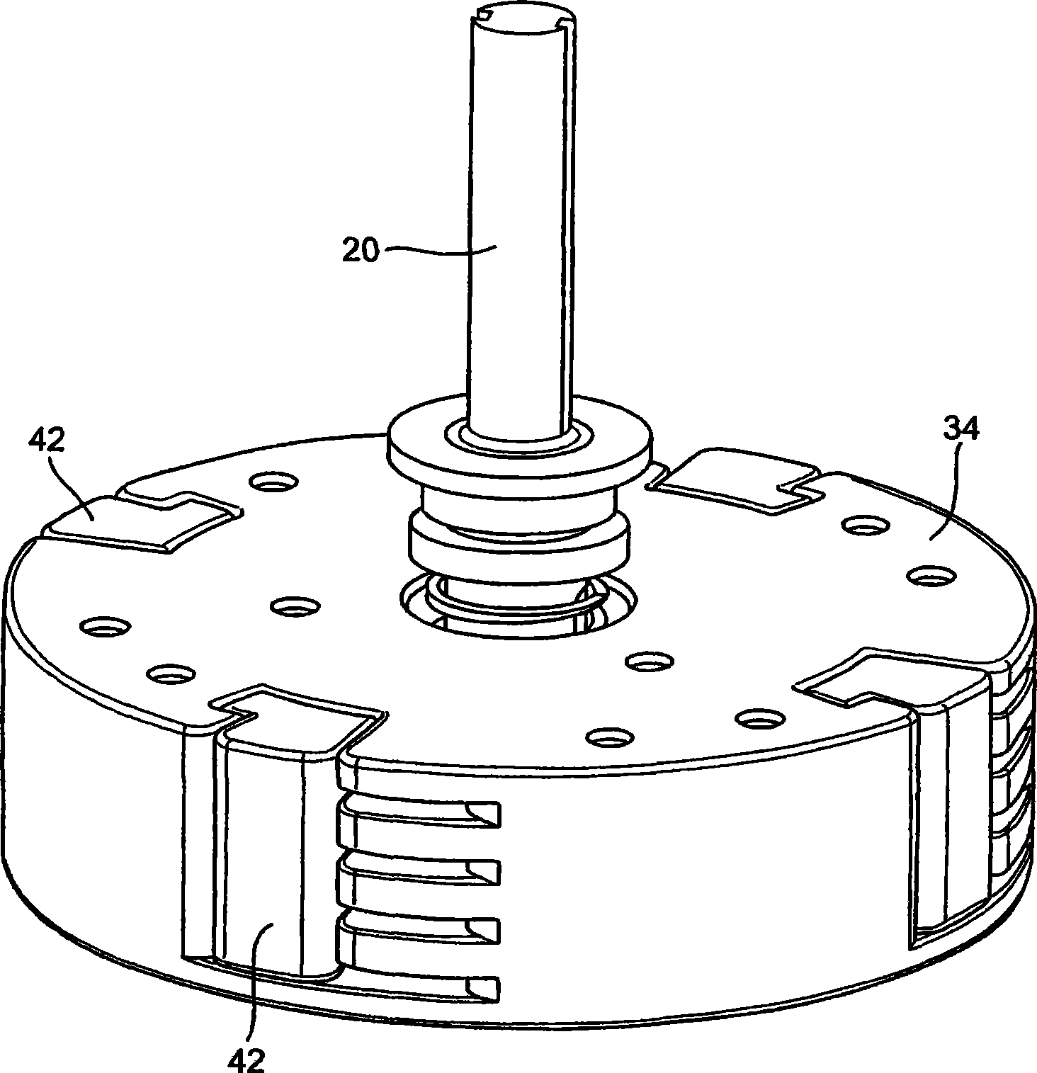
[0049] In the presence of an electric field, electrorheological fluids undergo changes in rheological properties such as viscosity. Such fluids are produced using a suspension of particles with a size of about 0.01 to 0.1 [mu]m in an insulating base fluid such as oil. The volume ratio of particles is usually between 20% and 60%. The electrorheological effect (sometimes called the Winslow effect) is thought to arise from the difference in dielectric constant between the fluid and the particles in electrorheological fluids (ERFs). In the presence of an electric field, the particles form chains along the field lines due to the induced dipole moments. The sensing structure changes the viscosity, yield stress, and other properties of the ERF, allowing the consistency of the ERF to change from a liquid to a viscoelastic-like consistency such as a gel within a millisecond response time. ERFs can exert very high electrically controlled resistance while being small in size (weight an...


PUM


Abstract

Electro-rheological fluid brake or actuator devices provide controllable resistance with or without inclusion of active torque output in either direction of rotation under manual or computer control. The brake and actuator devices are suitable for use in an orthotic device for a joint, such as the knee or elbow.

Description

[0001] Cross References to Related Applications [0002] This application claims priority to U.S. Provisional Patent Application No. 60 / 626,256, filed November 9, 2004, and U.S. Provisional Patent Application No. 60 / 626,365, filed November 9, 2004, the contents of which are incorporated by reference method is incorporated into this application. [0003] Statement Regarding Federally Sponsored Research or Development [0004] none Background technique [0005] Various types of actuators and brakes are known. For example, a DC motor can be used as an actuator to control the output torque. Such motors can be difficult to control for some applications and can be large and heavy. Increasing output torque usually requires increasing the size of the motor. For the above reasons and others, DC motors are not ideal in many applications for providing drag control or braking. As another example, friction brakes can be used for drag control, but not for output torque. On the downsi...

Claims


Application Information

Patent Timeline
IPC IPC(8): F16D57/00F16D41/00H01F7/06H01L41/00H02N2/00A61H1/00
Inventor B·温伯格J·尼基祖克C·马夫罗伊迪斯
Owner NORTHEASTERN UNIV
Why Eureka
Eureka Blog
Learn More